LANDING GEAR DOORS
aircraft structure. The principal components of each
latch mechanism, shown in figure 13-5, are a hydraulic
When installing new landing gear doors, you have
latch cylinder, a latch hook, a spring-loaded linkage,
to trim each door for a specific installation to obtain the
and a sector. The latch cylinder is connected
required clearances. The amount of material to be
hydraulically with the landing gear control system and
trimmed is determined by retracting the landing gear
mechanically, through linkage, with the latch hook.
(with the door linkage disconnected), and then
When hydraulic pressure is applied, the cylinder
releasing the hydraulic pressure. The up lock rollers on
operates the linkage to engage or disengage the hook
the doors are then removed to allow the doors to be
with or from the latch roller on the door. In the
closed, and yet not become locked in the closed
gear-down sequence, the hook is disengaged by the
position. With the landing gear doors held in the closed
spring load on the linkage. In the gear-up sequence,
position, each door's edge is marked where trimming is
spring action is reversed when the closing door is in
needed to maintain the specified clearances. The doors
contact with the latch hook, and the cylinder operates
are then opened and the excess amount of material
the linkage to engage the hook with the latch roller.
trimmed off. After you have completed the trimming
Cables on the landing gear emergency extension
and checked the doors for proper clearances, the
system are connected to the sector to permit emergency
landing gear is lowered and the door linkage and up
release of the latch rollers. An up-lock switch is
lock rollers are installed.
installed on, and actuated by, each latch to provide
main-gear-up indication in the cockpit.
The distance the landing gear doors open or close
depends upon the length of door linkage and
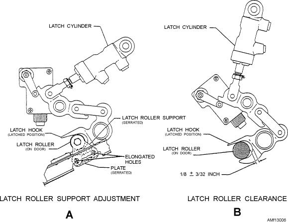
With the gear up and the door latched, inspect the
adjustment of doorstops. Maintenance instruction
latch roller for proper clearance. See view B of figure
manuals (MIMs) specify the length of door linkages
13-6. On this installation, the required clearance is 1/8
and adjustment of stops or other procedures whereby
inch 3/32 inch. If the roller is not within tolerance, it
correct adjustments may be made. On some models of
may be adjusted by loosening its mounting bolts and
aircraft that incorporate forward and aft landing gear
raising or lowering the latch roller support. This can be
doors, the doors are adjusted separately, and in some
done because of the elongated holes and serrated
cases, they are "pulled" or "warped" into a desired
locking surfaces of the latch roller support and serrated
shape.
plate. See view A of figure 13-6.
Figure 13-6.--Landing gear door latch installation.
13-7

