
the greatest possible amount of heat is dissipated
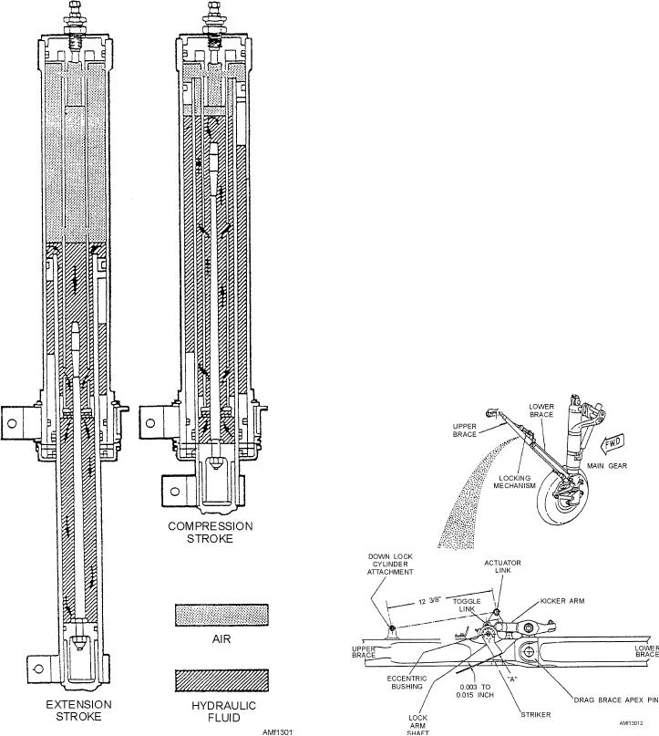
Figure 13-11 shows the inner construction of a
through the walls of the shock strut. At the end of the
shock strut and the movement of the fluid during
downward stroke, the compressed air or nitrogen is
compression and extension of the strut. The
further compressed, limiting the compression stroke of
compression stroke of the shock strut begins as the
the strut. If there is an insufficient amount of fluid
aircraft hits the ground. The center of mass of the
and/or air or nitrogen in the strut, the compression
aircraft continues to move downward, compressing the
stroke will not be limited, and the strut will "bottom"
strut and sliding the inner cylinder into the outer
out, resulting in severe shock and possible damage to
cylinder. The metering pin is forced through the orifice,
the aircraft.
and by its variable shape, controls the rate of fluid flow
at all points of the compression stoke. In this manner,
The extension stroke occurs at the end of the
compression stroke, as the energy stored in the
compressed air or nitrogen causes the aircraft to start
moving upward in relation to the ground and wheels. At
this instant, the compressed air or nitrogen acts as a
spring to return the strut to normal. At this point, a
snubbing or dampening effect is produced by forcing
the fluid to return through the restrictions of the
snubbing device (recoil valve). If this extension were
not snubbed, the aircraft would rebound rapidly and
tend to oscillate up and down because of the action of
the compressed air. A sleeve, spacer, or bumper ring
incorporated in the strut limits the extension stroke.
MECHANICAL LINKAGE
The landing gear drag brace, shown in figure 13-12
consists of an upper and lower brace that is hinged at
the center to permit the brace to jackknife during
retraction of the gear. The upper brace pivots on a
trunnion attached to the wheel well overhead. The
lower brace is connected to the lower portion of the
shock strut outer cylinder.
Figure 13-11.--Shock strut operation.
Figure 13-12.--Landing gear drag brace adjustment.
13-10