
Figure 17-12.--Automatic blade folding system schematic--Continued.
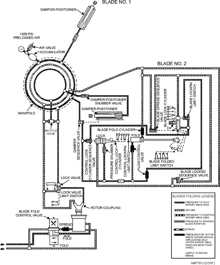
positioning the blades operates the damper-positioner
With the rotor head controls locked, pressure is sent to
sequence valves. These valves cause hydraulic fluid to
the blade fold lock cylinder. The lockpin is retracted,
operate the control lock cylinder, locking the controls.
and fluid is sent to the blade fold cylinder.
17-17