
sequence valve. This action occurs when the gear train
expansion and contraction of the hydraulic fluid
has been operated to disengage the rotor brake disc.
because of temperature changes. It also dampens out
pressure surges during fold and spread cycles.
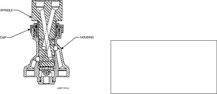
ROTOR COUPLING.--The rotor coupling is
found at the bottom of the rotary-wing shaft. It serves
AUTOMATIC BLADE FOLDING SYSTEM
to transfer hydraulic fluid to the rotary-wing head for
MAINTENANCE
blade folding. Figure 17-14 shows a cross-sectional
Maintenance of the blade fold system consists of
view of the coupling. The coupling consists of a
periodic inspection, lubrication, operational testing,
spindle that revolves with the rotary-wing shaft. A
and troubleshooting. Allowable maintenance at the
stationary housing connects to hydraulic lines of blade
organizational level includes alignment, adjustment,
folding components. Hydraulic fluid is sent through
and the removal and installation of components. Parts
the rotor coupling, and then through the lock valve.
replacement and cure date kits are available for
Pressure is then sent to the manifold, to the
intermediate-level repair of defective parts. Before
d a m p e r- p o s i t i o n e r s h u t t l e va l ve , a n d t o t h e
removal of any component, secure the blades to
damper-positioner sequence valves.
prevent damage. Whenever any part of the system is
CONTROL LOCK CYLINDER.--The control
repaired or replaced, the electrical portion of the
lock cylinder is on the No. 2 blade horn assembly
system should be tested, as required by the MIM.
rotary-wing head. During the fold cycle, the control
Operationally check the entire hydraulic portion of the
lock cylinder locks the flight controls. This occurs
system to ensure proper sequence of operation. The
only after the blade has been positioned. During the
hydraulic testing procedures discussed in the
spread cycle, it unlocks the controls. A microswitch
following paragraphs are used as an example. Always
within the housing of the cylinder causes the CONT
consult your MIM for correct procedures.
LOCKPIN ADV advisory light in the cockpit to light.
Charge the air accumulator with 1,500 psi of
In event of hydraulic malfunction, the control lockpin
nitrogen, with the blades in the spread position.
may be operated manually. This is done by turning a
Connect a source of external hydraulic power to the
sector gear bolt on the aft end of the cylinder. The
utility, primary, and auxiliary hydraulic systems. Set
sector bolt rotates gear teeth on the end of the actuating
pressure to 3,000 psi at approximately 3 gallons per
piston shaft.
minutes for the utility system. Set pressure to 1,500 psi
BLADE FOLD ACCUMULATOR.--A blade
for the primary and auxiliary servo hydraulic systems.
fold accumulator is found inside of the rotary-wing
Position the ACCESSORY DRIVE switch to ACCESS
sleeve of the No. 1 blade. It has a preload of 1,500-psi
DR. The accessory drive light will light. At the start of
nitrogen pressure to maintain hydraulic pressure in the
the testing, make sure that PRI SERVO PRESS, AUX
rotary-wing head. The pressure is necessary to keep
SERVO PRESS, ACCESSORY DRIVE, ROTOR
the damper-positioners extended and the blade locked
BRAKE ON, and CHECK BLADE FOLD lights will
in the folded position. It serves to compensate for
light. The ACCESSORY DRIVE, FLIGHT POS,
BLADE SPREAD, EXT PWR ON, PRI SERVO
PRESS, and AUX SERVO PRESS lights should be lit.
Visually check to see that the lockpins are disengaged.
Manually rotate the rotary head until the leading edge
of the No. 1 blade is in the aft position. Engage the
rotor brake. The rotor brake pressure gauge should
read a minimum of 320 psi. Check that the rotor brake
WARNING
Ensure that the path of the blade is clear
before tripping the manual override. Failure to
do so could result in personal injury or damage to
the aircraft. The cyclic control stick may have to
be moved slightly around neutral to engage the
control lockpin.
Figure 17-14.--Rotor coupling.
17-19