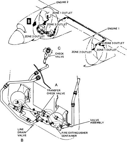
Drain Valves
no. 1 and no. 2 engine nacelles) or no. 2 (right wing, no.
3 and no. 4 engine nacelles). Each system has only two
Drain valves (fig. 5-23, item B) are provided in the
containers; one container for each engine or two
plumbing immediately forward and aft of each transfer
containers for the same engine. Either system is no
check valve, and when the tubing is routed from an
longer effective for fire extinguishing after the two
inboard engine to the wing front beam. A drain valve
containers in the system have been discharged. The two
constructed in the same manner as a check valve is
main plumbing lines from each container for a system
spring-loaded to the open position to drain any
are connected to transfer check valves and then to
condensation at the low points in the system plumbing.
outlets in the engine fire zones. Installed in the
When a container is discharged, pressure of the agent
plumbing between container and transfer check valve is
overcomes the spring force and closes the drain valve,
a test plug.
allowing all agents to go to the engine outlets. As
pressure is relieved in the tubing, the drain valve opens
COMPONENTS
under spring force.
Fire-extinguishing system components include
Check Valve
transfer check valves, drain valves, check valves, and a
container assembly.
Each engine nacelle zone has one
fire-extinguishing outlet. The outlets for zones 1 and 2
Transfer Check Valve
incorporate a check valve (discharge nozzle) (fig. 5-23,
A transfer check valve (fig. 5-23, item A) has two
item C) installed at the end of the plumbing outlet. Zone
inlet ports and one outlet port, and a poppet that shuts
3 has an unrestricted outlet.
off one inlet port. Therefore, only one inlet port is
Container Assembly
utilized for the direct position, and the other inlet port is
used for transfer position. There is no restriction on the
The container (fig. 5-24) is a welded steel sphere
outlet port.
approximately 9 inches in diameter, and is cadmium
Figure 5-23.--Engine fire extinguishing system schematic diagram.
5-20

