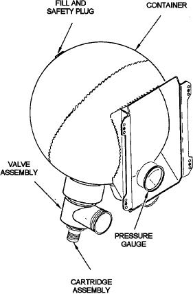
There are eight circuit breakers used in the engine
fire-extinguishing system. These circuit breakers are
located at the forward load center and supply 28 Vdc,
when a closed electrical path has been provided
through the discharge switch to ignite the cartridges in
the fire-extinguishing container and valve assembly.
Four emergency shutdown handles and four
fire-extinguishing discharge switches arm and dis-
charge the system. Normally, a discharge switch is not
actuated until the respective emergency shutdown
handle for that engine has been pulled aft. A protective
guard around the switch prevents inadvertent actuation
of the discharge button although the switch can be
pushed. With an engine fire indicated by the fire
warning lights on the fire-extinguishing control panel,
the respective and individual emergency engine
shutdown handle is pulled aft approximately 6 inches to
gain access to the discharge switch for the engine
nacelle indicating the fire.
As a specific example, if a fire is indicated in no. 3
engine nacelle, pull no. 3 engine emergency handle aft
and press the no. 3 engine fire-extinguishing discharge
Figure 5-24.--Fire extinguishing system container and valve
button. If the fire persists and it becomes necessary
assembly.
to discharge the second container of the same
fire-extinguishing system into no. 3 engine nacelle, the
transfer switch, which is guarded and shear-wired in the
plated for corrosion prevention. The internal volume of
DIRECT TO ENGINES position, must be set to
the container is 400 (+20, -15) cubic inches. The
TRANSFER TO ADJACENT ENGINES, and the no. 3
container is filled with 10.5 (+0.25, -0.00) pounds of
engine fire-extinguishing discharge button must be
fire-extinguishing agent and pressurized with nitrogen
pressed again. This action electrically ignites the
to 600 (+25, -0) psi. Total weight of the charge is 10.81
cartridge in the transfer container valve assembly of the
to 11.22 pounds including 0.47 pounds of nitrogen. A
second fire-extinguishing container in that system.
mounting bracket, which is welded to the container,
attaches to the forward face of the firewall and
The rate of discharge of a fire-extinguishing system
protrudes through the aft side of the firewall. Each
is approximately 0.4 seconds. All containers, distribu-
container is equipped with two valve assemblies to
tion lines, nozzles, and fittings are of stainless steel.
discharge a container; however, only one assembly is
fired at any one time to discharge a container. Each
AUXILIARY POWER UNIT (APU) FIRE
valve assembly contains a high-temperature
DETECTION AND EXTINGUISHING
electrically controlled dual squib cartridge with a slug
SYSTEM
attached.
The APU compartment fire detection and
OPERATION
extinguishing system provides automatic fire control
on the ground and in flight. The automatic system is
When a fire-extinguishing discharge switch is
backed up by audible and visual warnings and manual
actuated to complete the circuit, the cartridge is
release of the extinguishing agent. The warning light
electrically fired to allow its slug to rupture the
and MAN REL AUX PWR UNIT EXTINGUISHER
frangible disc in the neck of a container. A screen
switch are located adjacent to the no. 4 nacelle
adjacent to the disc retains the six frangible disc
discharge switch on the glareshield APU FIRE
segments when the cartridge is fired. The extinguishing
WARNING AND EXTINGUISHER panel. In addition
agent is expelled from the container. A safety disc plug
to the flight station warning horn, another identical
is installed inside the overboard discharge port and has
horn is located at the main load center, which is
a burst range of 1450 to 1800 psi at 200F.
5-21

