
are used to balance airflow when the APU/AMP
serves as a single source of air with a flow rate equal to
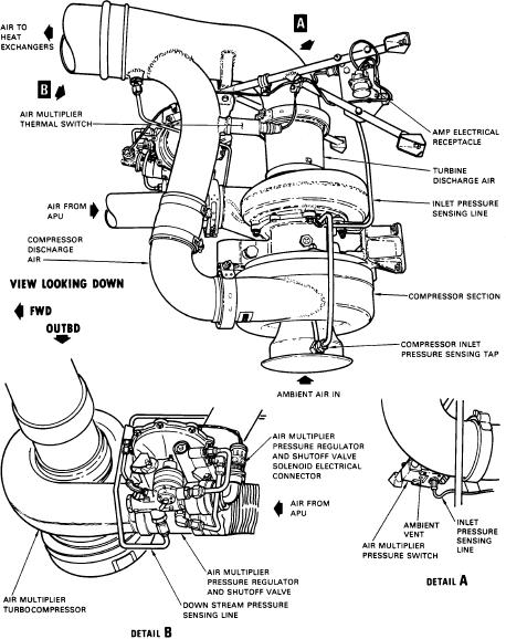
combination is the air supply source. Figure 6-2 shows
that supplied by the two EDCs. With the engines
an AMP installation.
operating at normal revolutions per minute (rpm), each
EDC supplies air to its respective air cycle cooling
COMPONENTS
system at the rate of approximately 60 pounds per
minute (lb/min). The APU/AMP combination supplies
Components include a heat exchanger package,
air to a duct common to both air cycle cooling systems
turbine refrigeration unit, water separator, water spray
at a rate of approximately 125 lb/min. The air volume
system, and a flow-limiting venturi.
divides in the air cycle cooling system interconnection
duct, with half going to the flight station air cycle
Heat Exchanger Package
cooling system and half to the cabin air cycle cooling
system.
The function of the heat exchanger package (fig.
An air-conditioning system that employs a single
6-3) is to reduce the temperature of the supply air
source of air to supply two air cycle cooling systems
furnished by the EDC or AMP. Two heat exchanger
that operate at different back-pressures will have air
packages, each consisting of a primary and secondary
flow problems unless a control is added to balance
section, electric fan assembly, check valve, and ram air
airflow. If airflow is not properly balanced, the air cycle
duct check valve are installed on each side of the nose
cooling system with the lower back-pressure (as the
wheel well. The left heat exchanger package supplies
result of more air bypass) will rob air from the unit with
air for the cabin systems and the right package cools
the higher back-pressure. Two flow-limiting venturis
flight station air.
Figure 6-2.--AMP installation.
6-4