
and temperature to the point where the air becomes
aircraft nose wheel well. The refrigeration unit, along
usable for aircraft cooling.
with the secondary section of the heat exchanger,
lowers the temperature of supply air so that it may be
Lubrication of the rotating assembly bearings is
used for aircraft cooling. The refrigeration unit consists
accomplished by an air-oil mist. Oil is absorbed by
of a rotating assembly and a housing assembly. The
wicks, which extend from the oil sump to the shaft of
rotating assembly mounts a turbine scroll and a
the rotating assembly. Oil is distributed on the rotating
compressor scroll, enclosing the rotating assembly. The
assembly shaft as a result of capillary action in the
bottom of the bearing support housing forms a sump for
wicks. Rotation of the shaft causes the oil to diffuse into
lubricating oil. A sight gauge is provided in the sump
an air-oil mist. The action of the oil slingers causes the
for determining the level of lubrication oil. Each of the
air-oil mist to pass through the bearings, providing
three sections formed by the housing assembly is sealed
lubrication.
to prevent air and oil leakage.
Water Separator
Compressed supply air, after it has passed through
the primary section of the heat exchanger, is ducted into
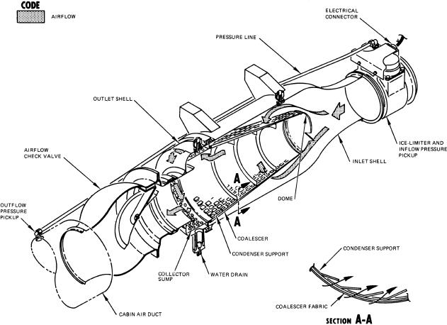
The water separator (fig. 6-5) removes moisture
the compressor section of the turbine where it is further
from the air before it is distributed within the aircraft.
compressed as it passes through the compressor scroll.
Two water separator units are installed in the APU
The compressed air, with a temperature slightly above
compartment. The cabin system unit is located in the aft
that of ambient air, is then routed to the secondary
upper left section of the APU compartment and the
section of the heat exchanger, where it is cooled to a
flight station unit is located in the forward upper right
lower temperature. Returning from the heat exchanger,
section.
the compressed air enters the turbine scroll, expanding
as it flows from the nozzle through the turbine wheel to
The water separator consists of a condenser assem-
the outlet duct. As the air is expanded, it drives the
bly and a collector assembly. The condenser assembly
turbine wheel at high speed. Mechanical energy, which
is a coalescer. An ice-limiting sensor is installed in the
is extracted from the air to drive the turbine wheel, is
inlet section of the unit to protect against icing and a
transmitted to and absorbed by the compressor wheel.
check valve is installed in the water separator outlet to
This mechanical energy reduces the supply air pressure
prevent reverse airflow through the unit.
Figure 6-5.--Dual check valve, water separator, and ice-limiting sensor.
6-6