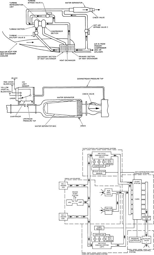
Figure 6-9.--Air cycle cooling schematic diagram.
back-pressure on the air cycle cooling system. High
back-pressure from the air cycle cooling system will
cause the pressure ratio across the EDC to exceed its
design limits and cause a compressor surge condition.
The compressor surge may cause a loss of cooling air at
the dump valve or damage the EDC. The ice limit
sensor, a pressure switch, senses the pressure differen-
tial across the water separator. One side of the pressure
switch senses the air pressure upstream from the water
separator bag, and the other side senses the air pressure
downstream from the water separator bag. When the
bag is covered with ice, the airflow is impeded and a
greater-than-normal pressure drop develops across the
bag. When the pressure differential exceeds 2.9 inches
mercury (Hg), a switch actuates in the ice limit sensor
ice limiter indicating partial blockage (yellow condi-
tion) of the water separator (fig. 6-9). If the water
separator icing condition worsens and the ice limiter
senses an increase in pressure drop across the water
separator bag to 4.1 inches Hg, the high-pressure switch
actuates in the ice limit sensor, indicating heavy block-
age (red condition) of the water separator. These ice
limiting sensor signals are used by the temperature con-
trol system, during the automatic mode only, to control
water during icing. Figure 6-10 shows the ECS flow.
Figure 6-10.--ECS block diagram.
6-11

