copper or aluminum alloy tubing is used in lines
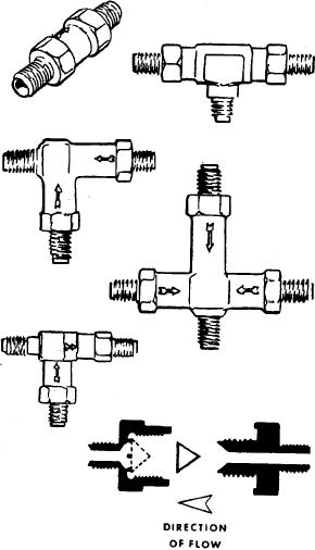
CHECK VALVES.--Check valves are installed at
carrying pressure above 450 psi.
various points in the oxygen system. Their purpose is to
permit the flow of oxygen in one direction only and to
Lines running from the filler valve to each of the
prevent the loss of the entire oxygen supply in the event
cylinders are called filler lines. Those running from the
a cylinder or line is ruptured.
cylinders to the regulators are called distribution or
supply lines.
Various styles of single, dual, and triple check
valves are available, as shown in figure 7-3. The arrows
Oxygen lines, like all other lines in the aircraft, are
embossed on the valve casting indicates the direction of
identified by strips of colored tape. The strips of tape
flow through the valve.
are wrapped around each line near each fitting and at
least once in each compartment through which the line
P R E S S U R E - R E D U C I N G VA LV E S . --
runs. The color code for oxygen lines is green and white
Pressure-reducing valves (or pressure reducers) are
with the words Breathing Oxygen printed in the green
used in certain oxygen systems for the purpose of
portion, while black outlines of rectangles appear in the
reducing high cylinder pressure to a working low
white portion.
pressure. In most installations the pressure reducers are
designed to reduce the pressure from 1,800 psi to a
Resistance to fatigue failure is an important factor
working pressure of 60 to 70 psi. They are always
in oxygen line design because the line pressure in a
located in the oxygen distribution lines between the
high-pressure system will at times exceed 1,800 psi,
cylinders and the flight station outlets. Figure 7-4
and at other times be as low as 300 psi. Because of these
illustrates a typical pressure-reducing valve.
varying pressures and temperature, expansion and
contraction occur all the time. These fluctuations cause
FILLER VALVES.--All oxygen systems are
metal fatigue, which must be guarded against in both
designed so the entire system can be serviced (refilled)
the design and the construction specifications for
through a common filler valve. The filler valve is
tubing. Steps are taken during installation to prevent
fatigue failure of the tubing. Tubing is bent in smooth
coils wherever it is connected to an inflexible object,
like a cylinder or a regulator. Every precaution is taken
to prevent the accidental discharge of compressed
oxygen because of faulty tubing or installation.
Although simple in construction and purpose, tubing is
the primary means by which oxygen is routed from the
cylinders to the regulator stations.
High-pressure tubing is used between the oxygen
cylinder valve and the filler connection in all systems,
between the cylinder valve and the regulator inlet in
high-pressure systems, and between the cylinder valve
and pressure reducer in reduced high-pressure systems.
To connect high-pressure copper tubing, adapters
and fittings are silver-soldered to the tubing ends. Due
to the high pressures involved, the security (leak
tightness) of all high-pressure lines relies primarily on a
metal-to-metal contact of all its fitting and connections.
A fitting properly silver-soldered to the end of a length
of copper tubing will not come loose or leak.
Valves
Various types of valves are installed in gaseous
oxygen systems. Among the most commonly used are
check valves, pressure-reducing valves, and filler
Figure 7-3.--Oxygen system check valves.
valves.
7-6

