
Each injector is fitted into a water-cooled copper
tube in the cylinder head and is held in place by an
injector clamp. It is operated by a push rod and rocker
arm. As the rocker arm forces the plunger down, the
upper helix closes the upper port, and fuel injection
begins. The upper helix and a lower helix are machined
TIMING
into the lower end of the plunger for metering purposes.
DIMENSION
The relation of these helices to the ports changes with
the rotation of the plunger. As the plunger moves
4
downward, a portion of the fuel trapped in the bushing
6
under the plunger is displaced through the lower port
back into the supply chamber, until the port is closed off
1
by the lower end of the plunger. A portion of the fuel
still trapped under the plunger is then forced upward
through the central passage of the plunger into the
recess between the two helices, and then into the supply
5
chamber through the upper port, until the upper helix
closes that port. With the upper and lower ports closed,
3
2
the remaining fuel trapped under the plunger is
subjected to increased pressure by the continued
downward movement of the plunger. When sufficient
pressure is built up, the injector valve is lifted off its seat
and the fuel is forced through small orifices in the spray
ASf04048
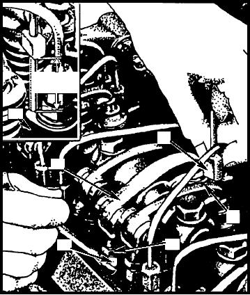
1. Rocker injector arm
4. Fuel injector
tip and atomized into the combustion chamber. The
2. Push rod
5. Injector follower
rotation of the plunger, by moving the rack, changes the
3. Locknut
6. Injector timing gauge
position of the helices and retards or advances the
closing of the ports and the beginning and ending of the
Figure 4-48.--Timing fuel injectors.
injection period. Fuel injection ends when the lower
helix opens the lower port. The remaining fuel then
case of 2-stroke cycle engines, are placed in the air
proceeds through the upper manifold, or outlet, back
passages surrounding the cylinders. The preheater
into the tank.
burns a small quantity of diesel fuel in the air prior to
the air being drawn into the cylinders. This burning
To properly time an injector, adjust the injector
process is accomplished by the use of either a glow plug
follower to a definite height in relation to the injector
or an ignition coil, which produces a spark to ignite a
body (fig. 4-48). This will vary according to the size of
fine spray of diesel fuel. The resulting heat warms the
the injector being used. Check the manufacturer's
remaining air before it is drawn into the cylinders.
manual to determine the proper gauge to use.
Glow Plugs
COLD WEATHER STARTING DEVICES
Glow plugs (fig. 4-49) are installed directly in the
Diesel fuel evaporates much slower than gasoline
precombustion or turbulence chamber of the cylinder
and requires more heat to cause combustion in the
head. The injection nozzle is also in this chamber.
engine's cylinders. For this reason, preheating devices
When you crank the engine, the glow plug is turned on.
and starting aids are found on all Navy equipment using
The heat created by electrical resistance in the glow
diesel engines. These devices and starting aids either
plug heats the fuel and air mixture. Heat generated by
heat the air before it is drawn into the cylinder or allow
the glow plug permits burning of the fuel in the
combustion at a lower temperature than during normal
chamber and cylinder.
engine operation.
Starting Fluid
Preheaters
Starting fluid, in either an aerosol container or
Preheaters, the most common type of heating
capsule, is frequently used as a starting aid. This fluid is
device, are installed in the intake manifold or, in the
a highly volatile fluid (ether or a suitable substitute),
4-36