
12
13
16
6
14
2
9
7
5
11
1
1
3
1
39
10
15
8
38
23
34
35
37
18
29
24
31
17
21
33
26
22
2
27
4
36
20
19
32
30
ASf10013
28
25
Nitrogen cylinders (2 each)
Boost pump
1.
21.
Oxygen cylinder
Exhaust (muffler)
2.
22.
Nitrogen cylinder valves
Pilot valve (normally closed)
3.
23.
Oxygen cylinder valve
4.
24.
Pilot valve (normally open)
High pressure manifold
Relief valve
5.
25.
Nitrogen supply pressure gauge
Purifier
6.
26.
Nitrogen supply valve
Filter
7.
27.
Oxygen vent valve
8.
28.
Preset regulator filter
Preset regulator
Regulator inlet pressure gauge
9.
29.
Low pressure manifold
Oxygen regulator
10.
30.
Low pressure rupture disc
Regulator outlet pressure gauge
11.
31.
Boost pump drive pressure gauge
Oxygen service connection
12.
32.
Ship/shop air connection
Servicing hose
13.
33.
Inlet air filter
Servicing valve
14.
34.
Boost pump drive valve
Servicing adapter connection
15.
35.
Boost pump drive vent
Low pressure servicing adapter
16.
36.
Nitrogen recharge connection
Low pressure adapter rupture disc
17.
37.
Recharge check valve
High pressure servicing adapter
18.
38.
Oxygen supply pressure gauge
High pressure adapter rupture disc
19.
39.
Selector valve
20.
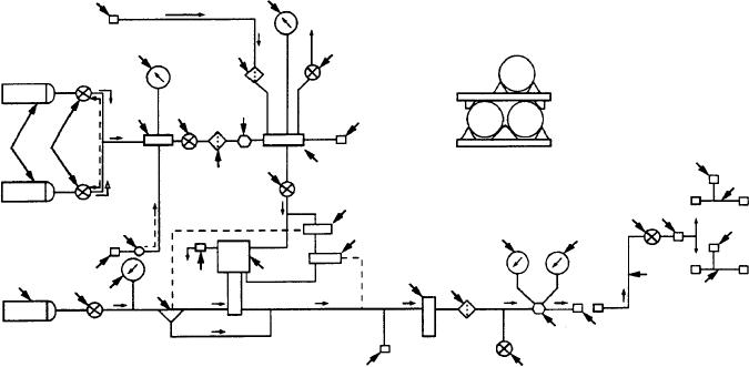
Figure 10-13.--Air/nitrogen boost pump drive and oxygen servicing flow schematic.
NOTE: A number or numbers within parentheses,
Nitrogen Cylinders.--As shown in figure 10-14,
the nitrogen cylinders (1) are mounted on the trailer
such as (1), will appear following a component name
assembly in a rack. They are held in place by crossbar
throughout the discussion on the oxygen servicing
retainers located at the front and rear of the trailer. Each
unit. This number, or numbers, will always refer to
cylinder is equipped with a valve (3) to shutoff nitrogen
figure 10-13, although other figures will also be
flow from the cylinder when the unit is not in
referenced.
operation. The cylinders are interconnected via hoses
and a high-pressure manifold (5) and grounded to the
GAS STORAGE SYSTEM.--The gas storage
trailer frame. Each cylinder contains 340 standard
system stores the oxygen and nitrogen used in the
cubic feet of Type 1 (gaseous), Class 1 (oil-free)
operation of the unit. It consists of one oxygen cylinder
nitrogen at a pressure of 3,500 psi when fully charged.
and nitrogen cylinders. (See figure 10-14.)
The nitrogen within the cylinders is used to drive an
NOTE: The number in parentheses following a
oxygen boost pump when compressed air drive is not
available.
component name refers to figure 10-13.
10-25