
driven member (turbine). Notice that the vanes of the
pump are radial to the shaft and set straight. The
turbine vanes are exactly the same as those of the
pump. Therefore, when the pump is turning much
faster than the turbine, the oil is thrown onto the vanes
of the turbine with considerable force, as shown by the
heavy arrows. The oil strikes the vanes of the turbine
and splashes, or bounces back, as shown by the smaller
2
1
arrows.
The "bounce back" effect actually opposes the oil
flow from the pump and causes inefficiency, or torque
loss. Thus, when there is a big difference in driving and
4
3
driven speeds, a good share of the driving torque is
5
used in overcoming the bounce back effect. This
OIL
bounce back effect becomes less and less as the speeds
FLOW
of the pump and turbine come closer together. At the
fluid coupling stage, the bounce back effect is
practically gone, resulting in a very good torque
coupling between the pump and turbine.
The torque coupling, on the other hand, is greatly
different in the torque converter. The torque converter
is designed to prevent, or reduce to a minimum, the
effects of oil bounce back. This is accomplished by the
use of one or more members, in addition to the pump
and turbine. The vanes of all the members are curved to
either aid in the torque coupling from one member to
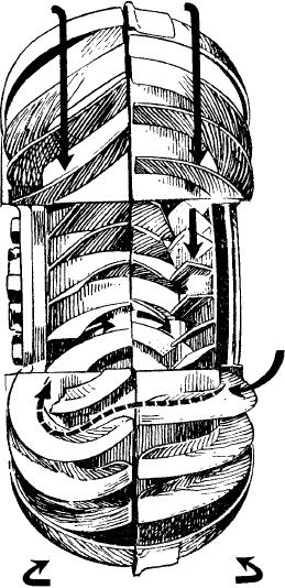
PUMP
TURBINE
ASf02052
another, or at least not to be a hindrance to this
Figure 2-52.--Torque converter, multi-element.
coupling. As a result of the torque converter design,
there is no torque loss when there is a large speed
the pump hurls the oil into the vanes of the turbine, but
difference between the pump and turbine. Quite the
because of the curvature of the vanes, the change in the
contrary--when there is a large speed difference, the
direction of the oil is gradual, thus reducing the effects
torque is increased, or multiplied, in the torque
of bounce back. As the oil passes through the turbine,
converter.
its direction is changed by the curved vanes so that it
The torque converter may be thought of as a special
leaves the trailing edges of the turbine vanes in a
form of fluid coupling that acts, in a sense, like a gear
direction to oppose the pump direction. This, in effect,
transmission with a large number of gearshift
would be worse than the bounce back effect of the fluid
positions. That is, it can transmit torque at a 1 to 1 ratio
coupling. However, the oil is again redirected before it
(direct drive); or under certain conditions, the
reaches the pump by the addition of a third member, a
converter can increase the torque so that more torque is
STATOR. The stator is a curved vane that redirects the
delivered than is applied. However, just as in a standard
oil from the turbine into the pump in a way that aids
transmission, if there is a torque increase there is a
rather than hinders its rotation. It is this aid caused by
speed reduction.
the stator that produces torque multiplication in the
The torque converter provides varying drive ratios
torque converter.
between the pump and turbine, thereby providing
Torque converter stator operation and the ability of
va r y i n g a m o u n t s o f t o r q u e i n c r e a s e . T h i s i s
the torque converter to multiply torque may be better
accomplished by the use of curved vanes in the pump
understood by studying figure 2-53. Figure 2-53
and turbine and by the use of one or more extra
illustrates the effects of a jet of oil on a flat piece of
members (elements). These additional members are
metal and on a bucket attached to a wheel. The oil jet
placed between the driving and driven members. The
will impart a terrific force against the flat piece of
vane curvature can be seen in the torque converter
metal, as shown in view A; however, notice the bounce
cutaway shown in figure 2-52. As in the fluid coupling,
2-42