
CENTER CAM
example, if the drive ring gear makes four revolutions
and the inner side gear, axle, and wheel make one
revolution, the outside wheel will rotate seven times.
If one wheel spins free from traction on a vehicle
using a conventional differential, the other wheel loses
power because the differential pinions are revolving
around the side gear of the stationary wheel and
applying all the power to the spinning wheel. This
result would be entirely unsatisfactory in towing
tractors; therefore, a no-spin differential is employed.
NO-SPIN DIFFERENTIALS
To provide the means of improving tractive effort
of the driving wheels when one wheel slips from loss of
traction, the differential must prevent actual slippage
and apply torque power to the driving wheels only to
the extent that the wheels can use the torque without
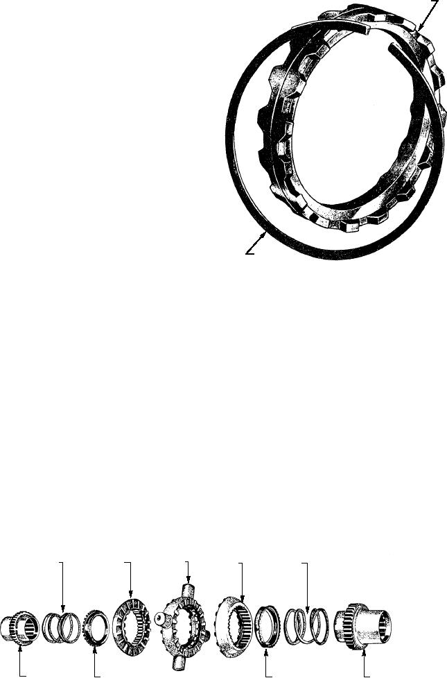
slipping. The no-spin differential (fig. 2-85) uses a pair
ASf02086
SPIDER
SNAP RING
of toothed clutches to do this. It does not contain side
gears as does the conventional differential. Instead it
Figure 2-86.--Construction of center cam.
contains a spider attached to the drive ring gear through
four differential pinions turning on the spider
must permit this action. As the left wheel begins to turn
trunnions, plus two driven clutch members with side
faster, the left-driven clutch member also turns faster
teeth that are indexed by spring pressure with side teeth
than the drive ring gear and spider speed. As the
in the spider. Two side members are splinted to the
left-driven clutch member begins to turn faster, the
wheel axles and, in turn, are splinted into the driven
cam lobes or ramps on its edge ride up on the cam lobes
clutch members.
on the center cam. This action pushes the left-driven
clutch member away from the spider so the clutch teeth
The center cam (fig. 2-86) in the spider is held in
place by a snap ring that permits the center cam to
disengage (fig. 2-88). As the crest of the ramp is
rotate, but does not permit it to move laterally. When
passed, spring pressure forces the teeth of the driven
making a right turn, the right-driven clutch member
clutch member back into full engagement with the
remains fully engaged with the spider clutch teeth (fig.
teeth on the spider. This action is repeated as long as
2-87).
the left wheel turns more rapidly than the right wheel.
Full drive is applied to the right wheel; no drive is
The spider clutch teeth (the driving teeth) drive the
applied to the left wheel. As soon as the vehicle
right (inside) wheel at drive ring gear speed. The left
completes the turn and the left wheel slows down to the
wheel (outside) covers a greater distance and must turn
right-wheel speed, driving power is applied equally to
faster than the drive ring gear speed. The differential
SPIDER AND
CENTER CAM
DRIVEN CLUTCH
DRIVEN CLUTCH
SPRING
SPRING
ASSEMBLY
MEMBER
MEMBER
ASf02085
SIDE
SPRING
SPRING
SIDE
MEMBER
RETAINER
RETAINER
MEMBER
Figure 2-85.--No-spin differential disassembled.
2-73