
unmeshed teeth, at the suction side of the pump, is
PLUG
carried by the teeth towards the sides. Then, the liquid
GASKET
is trapped between the tooth pockets and the casing, and
BOLT
SPRING
carried through to the discharge side of the pump. The
DRIVEN
BODY
GEAR
liquid entering the discharge side cannot return to the
RELIEF
suction side because the meshing teeth at the center
VALVE
DRIVEN
force the liquid out of the tooth pockets.
SHAFT
OIL
SEALS
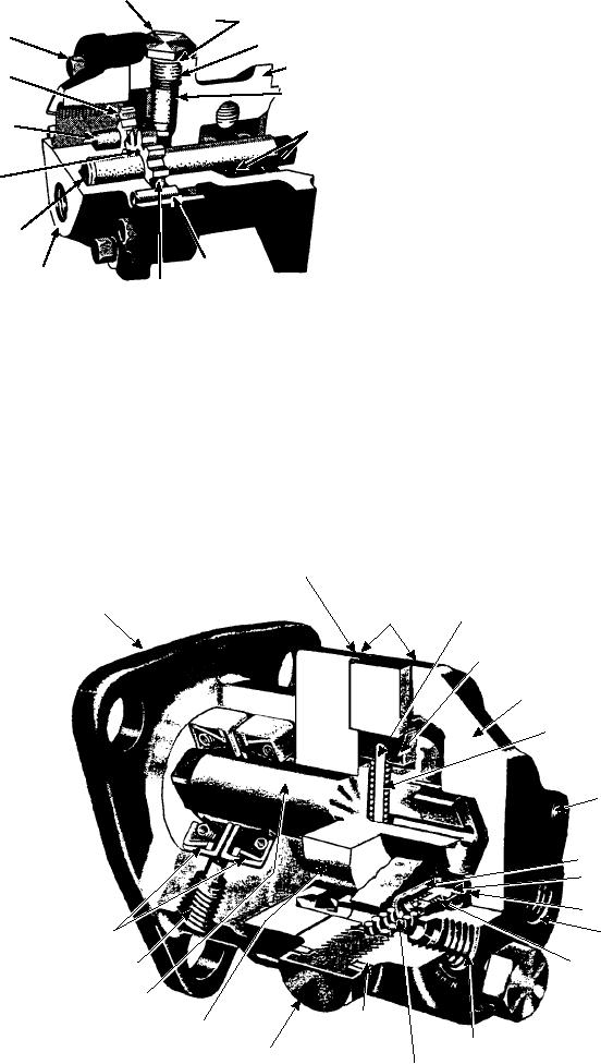
Vane Pumps
STEEL
BALL
In the vane-type pump (figs. 4-35 and 4-36), a steel
DRIVE
rotor and shaft, one end supported in the pump cover,
SHAFT
revolve in the body, the bore of which is eccentric to the
DOWEL
rotor. Two sliding vanes are placed 180 degrees apart in
COVER
ASf04034
DRIVE
slots in the rotor, and are pressed against the body bore
GEAR
by springs in the slots. When the shaft is rotated, the
vanes pick up fuel at the inlet port and carry it around
Figure 4-34.--Typical gear fuel pump assembly.
the body to the outlet side, where the fuel is discharged.
Pressure is produced by the wedging action of the fuel
as it is forced toward the outlet port by the vane. A
spring-loaded relief valve is provided in the cover of the
Gear Pumps
pump, connecting the inlet and outlet ports. This valve
opens at a pressure of approximately 55 psi. Its purpose
The simple gear pump (fig. 4-34) has two spur
is to relieve excessive pump pressure, which will build
gears that mesh together; one is the driving gear, the
up if fuel lines or filters become clogged. When the
other the driven gear. Clearances between the gear faces
valve opens, fuel passes from the discharge side
and casing are only a few thousandths of an inch. When
(pressure side) to the suction side of the pump.
the gears turn, liquid in the spaces between the
PUMP BODY
MOUNTING
FLANGE
GASKET
VANE SPRING
GUIDE
VANE
PUMP COVER
VANE SPRING
DOWELS
VALVE GAUGE
RELIEF VALVE
VALVE SEAT
OIL SEALS
OUTLET PORT
VALVE SPRING
DRAIN
ROTOR SHAFT
GASKET
PUMP ROTOR
INLET PORT
RETAINER SCREW
VALVE RETAINER
ASf04035
SPRING
Figure 4-35.--Cutaway view of vane-type fuel pump.
4-28