
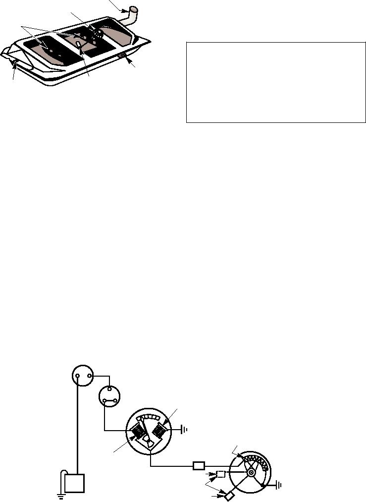
FILLER PIPE
leaks, they should not be welded or repaired with or
TA N K U N I T O F
ELECTRIC FUEL GAUGE
near an open flame until all traces of fuel and fuel
vapors have been completely removed from the tank.
BAFFLES
ASf04003
WARNING
FUEL LINE
Before attempting to make any repairs to a
CONNECTION
CORK
MOUNTING
fuel tank, always consult with the shop supervisor
TO CARBURETOR
F L O AT
FLANGE
for specific instructions on all safety precautions
to be observed. Remember that fuel tanks can be
Figure 4-3.--Fuel tank with top cut away.
extremely dangerous.
construction of the equipment. Figure 4-3 shows the
Fuel Gauges
general construction of a fuel tank used on automotive
equipment. Most fuel tanks are of similar construction.
The fuel gauge is a signaling system that indicates
They are usually made of rust-resistant sheet metal, and
the amount of fuel in the tank. Most fuel gauges are
have an inlet or filler pipe and an outlet. The outlet, with
electrically operated and are composed of two units: the
a fitting for the fuel-line connection, may be in the top
gauge itself, which is mounted on the instrument panel
or side of the tank. The lower end of the outlet pipe is
of the vehicle; and the sending unit, which is mounted
placed about one-half inch from the bottom of the tank
on the fuel tank. An electrical fuel gauge normally
so that any sediment that collects in the tank will not be
operates only when the ignition switch is turned on.
carried to the carburetor. Baffle plates may be placed
The tank unit of the balancing coil-type fuel gauge
inside the tank to reinforce the sides and bottom and to
(fig. 4-4) has a float and arm assembly connected to a
prevent the fuel from surging or splashing. A drain plug
sliding contact. As the fuel level in the tank changes, the
is placed in the bottom so that the tank can be drained
position of the contact changes on a rheostat winding,
and cleaned. The fuel tank must be equipped with an air
thus varying circuit resistance and resulting current
vent. This vent is usually located in the cap of the inlet
flow. The unit on the instrument panel contains two
pipe.
magnetic coils (limiting coil and operating coil) and a
Some vehicles, especially aircraft tow tractors, may
permanent magnet, which is attached to the gauge
have more than one tank. On these vehicles, the
needle. When the fuel tank is empty, the limiting coil is
auxiliary tanks are interconnected, and the flow of fuel
stronger than the operating coil, thus the magnet is
from one or more of the tanks may be turned off.
drawn toward it and the needle reads EMPTY on the
Fuel tanks give little or no trouble, and, as a rule,
gauge. As the tank is filled, the operating coil becomes
require no servicing other than an occasional draining
stronger, attracting the magnet and moving the needle
and cleaning. However, if they are punctured or develop
toward the F or FULL position.
IGNITION SWITCH
GAUGE
OPERATING
F
COIL
E
LIMITING
RHEOSTAT
COIL
CONNECTOR
PARTLY FULL POSITION
FLOAT
BATTERY
EMPTY POSITION
SENDING UNIT
ASf04004
Figure 4-4.--Coil-type gauge circuit.
4-4