
LEFT
HORN RELAY
RIGHT
FRONT
FRONT
LIGHT
LIGHT
HORN
HORN BUTTON
LEFT
RIGHT
INDICATOR
INDICATOR
H
B
LIGHT
LIGHT
LEFT TERMINAL
RIGHT TERMINAL
BATTERY
HORN
BLOCK
BLOCK
ASf06088
Figure 6-88.--Dual horns and relay circuit.
RIGHT
FLASHER
LEFT
relay is shown in figure 6-88. By having a relay in the
DIRECTIONAL SIGNAL
FUSE
LEVER
horn circuit, the contacts of the horn button (switch) are
protected, and many more hours of trouble-free service
IGNITION SWITCH
are obtained than with a horn circuit that does not have
a relay.
LEFT
RIGHT
DIRECTIONAL (TURN) SIGNALS
REAR
REAR
LIGHT
LIGHT
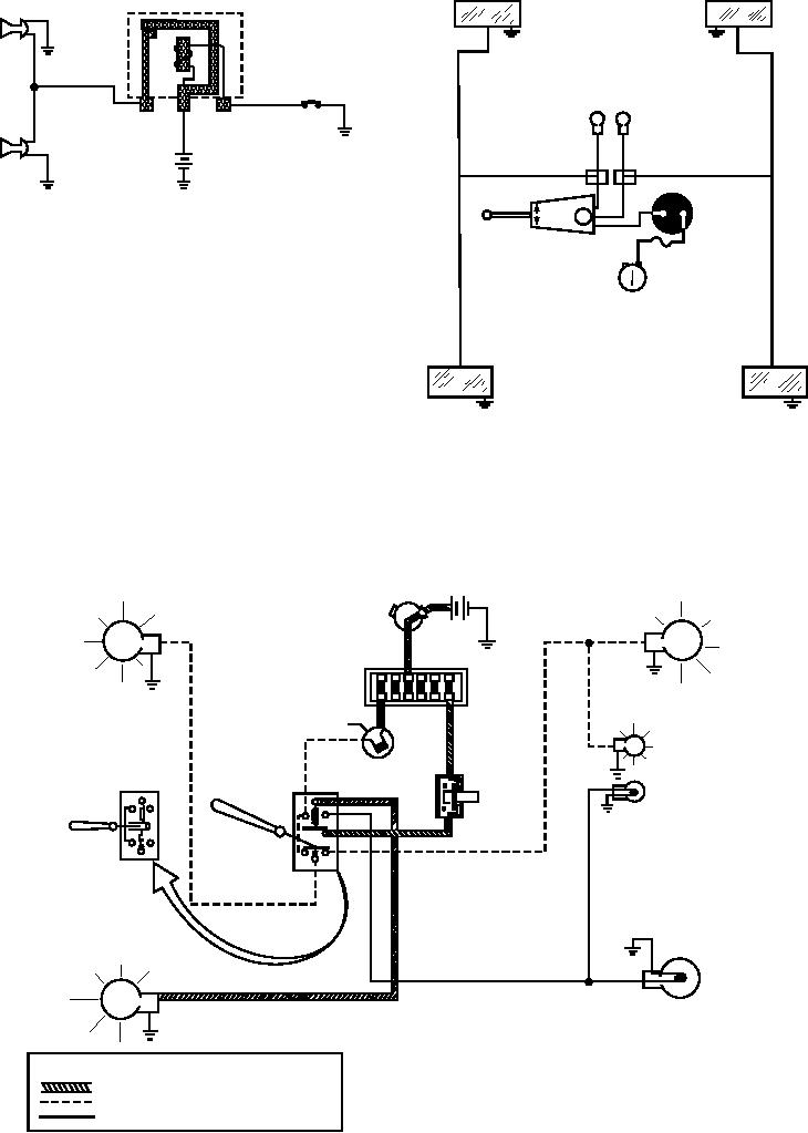
The directional signals (fig. 6-89) permit the
ASf06089
Figure 6-89.--Pictorial diagram of a directional signal system.
operator to signal his intention to make a right or left
turn. The direction of turn is indicated by flashing lights
contain a second filament, which is used in the parking
on the front and rear, and sometimes on the side of the
light system. Indicator lights are installed on the
vehicle. The rear lights are red in color and part of the
instrument panel of the vehicle to provide the operator
stoplight system. The front directional signals are
with the following indications:
usually white or amber in color. Both the front and rear
The direction of the turn.
lamps (bulbs) of the directional signal system normally
RIGHT REAR STOP
RIGHT FRONT
IGNITION
BATTERY
DIRECTIONAL LIGHT
DIRECTIONAL
SWITCH
(FLASHING)
LIGHT
ON
(FLASHING)
FUSE
BLOCK
DIRECTIONAL
SIGNAL
FLASHER
STOP
RIGHT DIRECTIONAL
LIGHT
INDICATOR LIGHT
SWITCH
(FLASHING)
(BRAKES
DIRECTIONAL SIGNAL
APPLIED)
SWITCH
LEFT DIRECTIONAL
OFF
(IN NEUTRAL
INDICATOR LIGHT
POSITION)
ON
DIRECTIONAL
SIGNAL
SWITCH
(IN RIGHT TURN
POSITION)
LEFT FRONT
LEFT REAR STOP
DIRECTIONAL
DIRECTIONAL LIGHT
LIGHT
(ON STEADY)
LEGEND
CONSTANT VOLTAGE
INTERMITTENT (FLASHING) VOLTAGE
NO VOLTAGE
ASf06090
Figure 6-90.--A representative stop-directional light system.
6-72