
transmission. The tachometer transmitter is usually
then automatically zero themselves. Also, they are
driven from an engine accessory drive, such as the
usually equipped with a reset mechanism so that the
ignition distributor drive. The output voltage of a
mileage on the trip odometer can be reset as desired.
transmitter is proportional to the speed at which it is
ELECTRICAL S P E E D O M E T E R S A N D
driven; likewise, the speed of a receiver is proportional
TACHOMETERS.--Electrical speedometers and
to the output voltage of the transmitter. The receiver
tachometers use a small generator (transmitter) that is
speed determines the position of the pointer on the face
mechanically driven. The voltage produced causes a
of the indicator.
synchronous motor (receiver) in the indicator assembly
to operate, thereby indicating vehicle and engine speed.
HORNS
There may be several different arrangements or
The horn installed on support equipment is used as
combinations of the electrical speedometer and
a warning device to pedestrians or crew members of a
tachometer. For instance, the speedometer and
moving vehicle. The horn is a magnetic switch
tachometer may be two completely independent
(somewhat like a vibrating voltage regulator relay),
systems, or there may be one transmitter and one
which sets a diaphragm into rapid vibration when
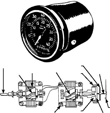
receiver with a dual face, as shown in figure 6-86. If this
connected to the battery. Horns may be used in matched
instrument is used on a vehicle and driven by gears in
pairs so that a blended and more resonant signal is
the transmission, the tachometer will be inaccurate
produced.
until a certain gear, normally high gear, is reached.
Another arrangement involves two transmitters--one
Operation
driven by the transmission for vehicle speed, and one
driven by the engine for engine rpm. This type of
The most common type of horn (fig. 6-87) is the
arrangement uses one indicator containing two
vibrator type. A winding is connected in series with a
receivers with independent pointers and dials. With this
set of contacts within the horn. The contacts are closed
arrangement, both the speedometer and the tachometer
when the horn is not energized.
are accurate in any gear.
When the external circuit to the battery is closed
The speedometer transmitter is driven from the
(by the horn push button or horn relay), current flows
final drive of the vehicle, usually the output shaft of the
through the contacts and winding. This causes the
HAIRSPRING
DRIVE SHAFT
ROTOR
STATOR
STAFF
IRON RING
ROTOR
POINTER
MAGNET
STATOR COILS
DRAG-CUP
SPEEDOMETER OR TACHOMETER
SPEEDOMETER-TACHOMETER
TRANSMITTER ASSEMBLY
INDICATOR ASSEMBLY
ASf06086
Figure 6-86.--Electrical speedometer-tachometer.
6-70