rather than a gauge indicating system. The warning
temperature and the gas flows through the capillary, a
light is usually controlled by switches that may be
very small tube connecting the bulb to the gauge. The
operated by pressure, temperature, or mechanical
greater the heat, the more vapor is given off and the
linkage. You will encounter vehicles that use either a
greater the pressure; thus, higher temperature is
warning light system or a combination of warning light
indicated on the gauge.
and gauge systems.
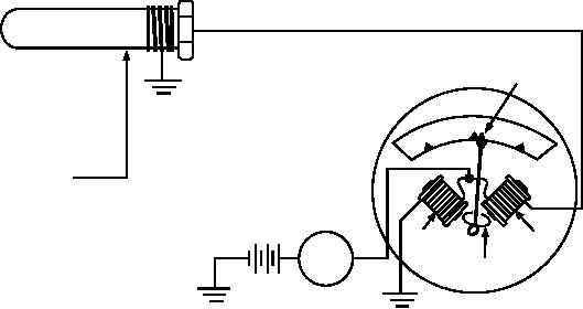
ELECTRICAL TEMPERATURE GAUGE.--
NOTE: To provide a means of testing the warning
The electrical temperature gauge (fig. 6-79) functions
lights, they are usually wired so that they illuminate
on much the same principle as the balancing coil fuel
when the ignition switch is placed in the starting
gauge and oil pressure gauge.
position.
The temperature gauge consists of two coils at right
angles to each other with an armature at the intersection
TEMPERATURE LIGHT.--Most late model
of the coil axes. Connected to the armature is a pointer.
vehicles use an engine temperature warning light
The sending unit is a resistor whose resistance varies
(located on the instrument panel) in place of the
inversely with the temperature of the engine. When the
conventional engine temperature gauge. The warning
engine temperature is high, the sender's resistance is
light is wired in series with the ignition switch and the
low; when the temperature is low, the resistance is high.
engine temperature sending unit. The sending unit
On the low-temperature side of the gauge unit, the coil
provides ground for the warning lights when its
is connected directly across the battery. Thus, there
contacts are closed. There are two systems for the
exists a constant magnetic strength in that coil, which
temperature warning lights that are commonly used.
attracts the armature and pointer to the low-temperature
One of the systems contains a cold light (green) and
side. However, the coil on the high-temperature side is
a hot light (red). These lights are controlled by the
connected in series with the resistance of the sending
engine temperature sending unit, which has two sets of
unit and across the battery. Since the sender's resistance
contacts, one set being normally closed for the cold
varies with temperature, the coil's magnetic strength
light and one set being normally open for the hot light.
varies. More current flows when the resistance is low
The contacts are mounted on bimetal strips, which
(high engine temperature), and so a stronger magnetic
cause them to open and close at predetermined
field is created. As engine temperature increases, the
temperatures. For example, when the engine is first
greater magnetic strength of the high-temperature coil
started, the cold light comes on until the engine reaches
attracts the armature and pointer to a point of balance
normal operating temperature. Then, the cold light
between the two sides. The scale is calibrated to the
switch contacts open and the light goes off. This lets the
pointer movement.
operator know that it is safe to apply load to the engine,
which is then at normal operating temperature.
Warning Lights
Likewise, if the engine overheats, the hot light switch
contacts close and the hot light comes on, warning the
Some automotive manufacturers prefer a warning
operator of the overheating condition.
light system that indicates certain operating conditions,
POINTER
ENGINE UNIT IS
180
IMMERSED IN
22
0
12
ENGINE COOLANT.
0
RESISTANCE OF
UNIT DECREASES
WITH HEAT
BATTERY
COIL
COIL
ARMATURE
IGNITION
DASH UNIT
ASf06079
SWITCH
Figure 6-79.--Electrical temperature gauge.
6-65

