
The other system mentioned operates on the same
principles but does not have a cold warning light. It has
the hot warning light and an engine temperature
1
_
sending unit with a single set of normally open
10
contacts. If the engine overheats, the contacts close and
turn on the hot warning light.
014375
OIL PRESSURE LIGHT.--The oil pressure
TOTAL HOURS
warning light installed on some vehicles is also located
on the instrument panel to indicate when the oil
pressure is very low. The warning light is wired in
series with the ignition switch. The oil pressure switch
is located on the automotive engine.
A
The oil pressure switch contains a diaphragm and a
0
set of contacts. When the ignition is turned on, the
1 HO
9
warning light should illuminate, because the light
1
UR
10 H
RS
circuit is energized through the closed contacts in the
100
HR
S
oil pressure switch. When the engine is started, built-up
8
2
oil pressure compresses the diaphragm, opening the
contacts, and thereby opening the circuit and causing
the warning light to go out. The warning light is usually
red and indicates a bright "Oil" on the instrument panel.
7
3
ALTERNATOR LIGHT.--Some vehicles use an
alternator warning light mounted on the instrument
6
4
panel in place of the ammeter. The light indicates to the
5
operator when the alternator is not charging the battery.
B
The warning element is a panel-mounted window
(usually red) behind which is mounted a small light
0
bulb. The light comes on when the ignition is turned on
10 HO
9
1
U
RS
and the alternator is not charging. The circuit is
100
HR
S
1000
HR
completed from the ignition switch, through the light,
S
to a terminal on the indicator light relay.
8
2
When the engine is running, the alternator speed is
sufficient to provide a voltage higher than that of the
battery. The operating coil of the indicator light relay
7
3
will be energized, opening the circuit between the
indicator light and the battery.
6
4
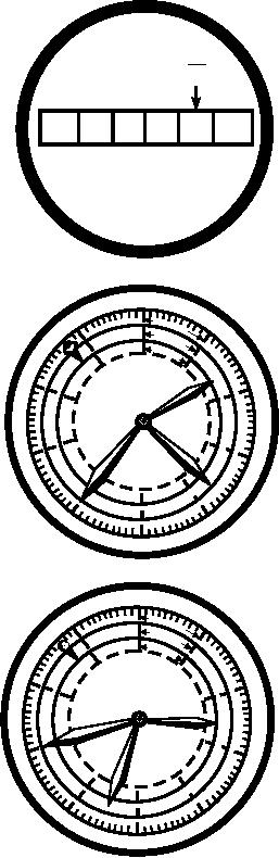
Hour Meter
5
C
Some support equipment requires servicing or
ASf06080
maintenance after operating a certain amount of time.
Figure 6-80.--Hour meters.
Hour meters (fig. 6-80) provide maintenance personnel
a means of determining the specific amount of time the
equipment has operated. With the information from the
electrically driven type records elapsed time (clock
hour meters and maintenance instructions, mainte-
hours). The mechanically driven type records time after
nance personnel can determine what maintenance is
a certain number of functions have taken place. For
required and when to perform it.
example, the hour meter may be designed to advance an
hour after the crankshaft of an engine has completed as
There are two types of hour meters commonly used
many revolutions as it normally would during an hour's
on support equipment. These are the electrically driven
operation.
(most common) and the mechanically driven types. The
6-66