
B
50mA
+
BAND
40mA
MARKED
30mA
+
MARKED
20mA
+
COLOR
SPOT
10mA
ANODES
CATHODES
A
GLASS
80V
40V
1V
2V
3V
4V
C
FORWARD BIAS
500uA
COLOR BAND
1000uA
GLASS
1500uA
ASf06004
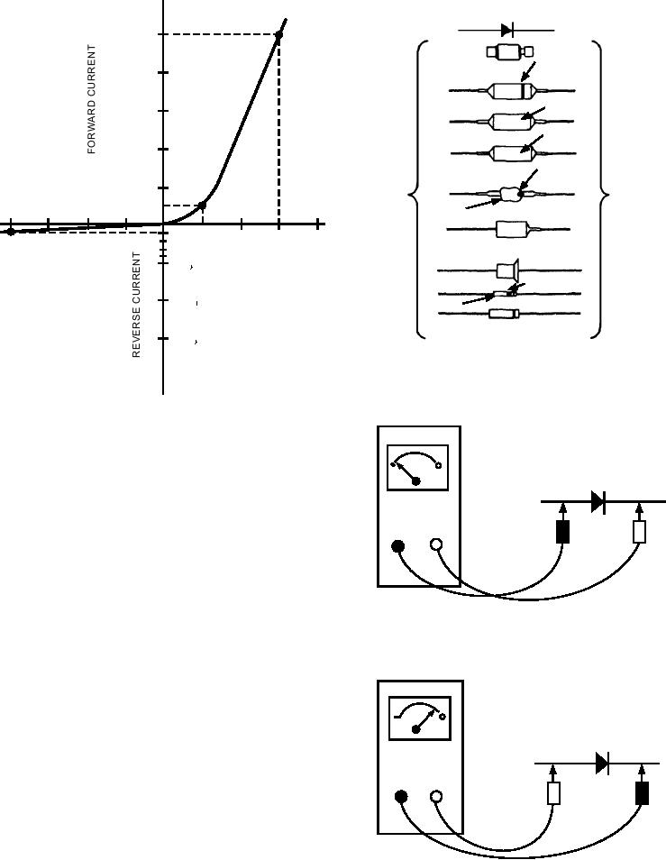
Figure 7-4.--PN diode identification.
ASf07003
Figure 7-3.--PN junction diode characteristic curve.
OHMMETER
barrier gets smaller, and its resistance to current flow
decreases.
On the other hand, the diode conducts very little
when reverse biased. Notice at point C the reverse bias
voltage is 80 volts and the current is only 100 A. This
TEST
results in 800 kilohms of resistance, which is
LEADS
considerably larger than the resistance of the junction
with forward bias. Because of these unusual features,
the PN junction diode is often used to convert
alternating current into direct current (rectification).
REVERSE CONDITION-
Figure 7-4 illustrates various styles of PN diodes.
H I G H R E S I S TA N C E M E A S U R E M E N T
To test a diode, you use a multimeter or ohmmeter.
Disconnect one of the diode leads from the circuit.
OHMMETER
Connect the meter to the diode's pigtails. Figure 7-5
illustrates the test. You may or may not get a reading.
Reverse the leads. If you had a low reading the first
time, you should now have no reading or a high
reading. A second low reading means the diode is
shorted. Two high readings after reversing the leads
TEST
LEADS
means the diode is open. A low reading and high
reading means the diode is good. One thing you should
keep in mind about the ohmmeter check--it is not
conclusive. It is still possible for a diode to check good
under this test, but break down (temporarily fail) when
F O RWA R D C O N D I T I O N -
replaced in the circuit. This can occur because the
L O W R E S I S TA N C E M E A S U R E M E N T
meter used to check the diode does not load the device
ASf07005
Figure 7-5.--Checking a diode with an ohmmeter.
as though it was in its operating circuit.
7-3