
ANODE
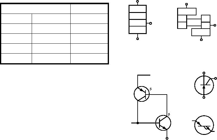
Table 7-1.--Transistor Problems
ANODE
P
RESISTANCE READING
PROBLEM
P
N
N
N
FORWARD
REVERSE
The transistor is:
P
GATE
GATE
P
P
Low (not shorted)
Leaking
N
N
Low (shorted)
Low (shorted)
Shorted
CATHODE
CATHODE
High
High
Open
A
B
Nearly Equal
Nearly Equal
Defective
CATHODE
ANODE
By now, you should recognize that the transistor
GATE
used in figure 7-12 is a PNP transistor. If you wish to
Q1
test an NPN transistor for leakage, the procedure is
1
identical to that used for testing the PNP, except the
readings obtained are reversed.
ANODE
PNP
COMMERCIAL
When testing transistors (PNP or NPN), you
should remember that the actual resistance values
2
Q2
depend on the ohmmeter scale and the battery voltage.
GATE
Ty p i c a l f o r w a r d a n d r e v e r s e r e s i s t a n c e s a r e
insignificant. The best indicator for showing whether a
NPN
MILITARY
transistor is good or bad is the ratio of
CATHODE
C
forward-to-reverse resistance. If the transistor you are
ASf07013
D
testing shows a ratio of at least 30 to 1, it is probably
Figure 7-13.--Silicon-controlled rectifier--(A) physical PNPN
good. Many transistors show ratios of 100 to 1 or
structure; (B) two transistor analogy; (C) SCR
greater.
internal circuitry; (D) SCR symbols.
SILICON-CONTROLLED RECTIFIERS.--
7-13.) As the overall gain approaches one and the SCR
The silicon-controlled rectifier (SCR) is a PNPN
starts to regenerate, each transistor drives its mate into
semiconductor switch, whose bi-stable action depends
saturation. Once in saturation, all junctions assume
on regenerative internal feedback. Once this rectifier is
forward bias, and the voltage drop across the device
turned on by a trigger voltage, it remains on until the
becomes very low.
supply voltage is removed. (See figure 7-13.)
This type of device is used in applications where a
The heart of a PNPN (SCR) device is its four-layer
very small "gate" voltage can be used to control high
structure, which consists of alternate P- and N-type
p ow e r r e q u i r e m e n t s , s u c h a s m a i n l i n e
semiconductor material (fig. 7-13, view A). A PNPN
power-contactor relays. The symbol for the SCR is
structure is best visualized as consisting of two
shown in view D of figure 7-13.
transistors, a PNP, and an NPN interconnected to form
a regenerative feedback pair, as shown in view B of
MAGNETIC AMPLIFIERS
figure 7-13. The overall gain of the SCR is equal to the
product of the gains of the two transistors. With proper
The advantage of the magnetic amplifier is that it is
voltage applied, the overall gain is less than one
a completely static device. With the exception of the
(unity). Under this condition, the SCR is said to be in
rectifiers normally used, its mechanical construction is
its forward blocking or "off" state, and the only current
comparable to that of an iron-core transformer. There
flow in the device is leakage current. The "on" or
are no moving contacts, moving parts, filaments, or
conducting state of the SCR is initiated simply by
other features that account for most of the failures
raising the overall gain to one (unity). This gain
associated with other types of amplifiers (except for
increase is caused by applying a voltage (which may be
those using transistors). A magnetic amplifier is
a short duration voltage pulse) to the base of one of the
essentially a device that controls the inductive
transistors or "gate connection." (See view C of figure
reactance of a coil by using a dc signal voltage to
7-7