
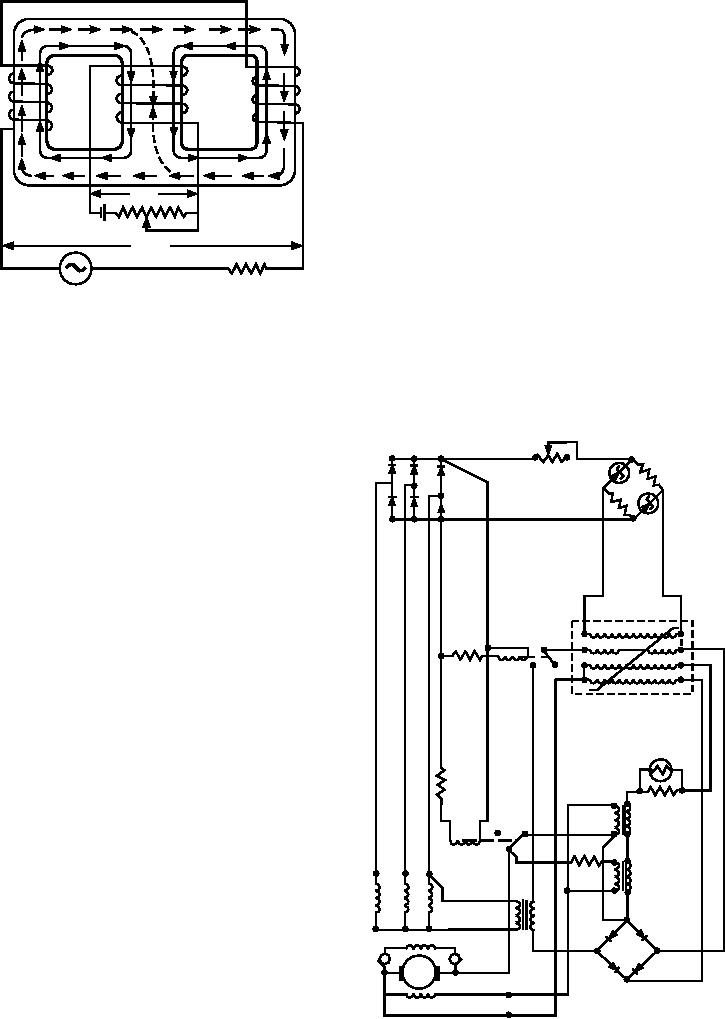
Figure 7-19 shows a typical solid-state voltage
regulator, using diodes, Zener diodes for voltage
sensors, and the magnetic amplifier.
and K2 are in the positions shown. During the initial
buildup of voltage, the residual dc output of the exciter
armature is connected directly to the exciter control
field through terminal A+ and K2, through the lower
winding of stabilizer transformer T4, and then through
_
DC
F+ to the field. This causes a rapid buildup of ac output
+
voltage through T1, T2, T3, and through the primary
w i n d i n g o f T 6 . W h e n l i n e vo l t a g e r i s e s t o a
AC
_
near-normal level, the output of CR1 is sufficient to
+
actuate relays K1 and K2. With the contacts of K2
ASf07018
AC SOURCE
R L (LOAD)
pulled down, exciter output no longer goes directly to
Figure 7-18.--Magnetic amplifier with three-legged core.
the exciter control field, but instead goes through a
the load windings are balanced out in the center leg and
current limiting resistor, T5 to A-. It is used thereafter
do not affect the control circuit.
as a stabilizer reference for normal operation. With the
contacts of K1 pulled down, the output of T6's
While alternating flux does not pass effectively
secondary is routed through the load windings 3-4 of
through the center leg, the two components add along
the magnetic amplifier L1 to rectifier CR2. The output
the path through the outer legs of the core, as indicated
by the broken lines. The drawing also shows that the
control current produces a magnetic flux (represented
CR1
R1
by solid lines) that magnetizes the entire core of each
BRDG 1
load winding. In this arrangement, the dc coil can
influence the operation of the load circuit. There is no
coupling of energy by transformer action from the load
circuit to the control winding.
During normal operation, variations of the control
L1
current result in corresponding changes in core
permeability; this readjusts the inductive reactance in
K1
series with the load. The operational control process of
this amplifier is very similar to that of the basic
R2
magnetic amplifier.
The efficiency of this magnetic amplifier can be
further improved by the use of rectifiers and bias
windings. The rectifiers are used to eliminate the
alternating flux in the core caused by the load current.
R3
The bias winding is used to preset a magnetic flux in
TC1
the core material. This aids the control winding in
T4
K2
controlling the permeability of the core.
T3
T1
T2
APPLICATION OF SEMICONDUCTOR
T5
DEVICES AND MAGNETIC AMPLIFIERS
X
T6
The magnetic amplifier and semiconductor
S
P
GEN. FIELD
devices have found widespread use in many different
CR2
EXC.
types of circuits. Circuits using these components may
A+
ARM
F+
Y
be found in voltage regulators, servo amplifiers, and
EXC. CONT. FIELD
A-
audio amplifiers. You are mainly concerned with their
ASf07019
application in voltage regulators.
Figure 7-19.--Typical solid-state regulator.
7-11