
DIRECTION OF
INDUCED CURRENT
NORTH POLE
OF MAGNET
B
DIRECTION OF
CONDUCTOR MOTION
A
LINES OF
ASf07022
FORCE
SOUTH POLE
OF MAGNET
Figure 7-22.--Electromagnetic induction principles.
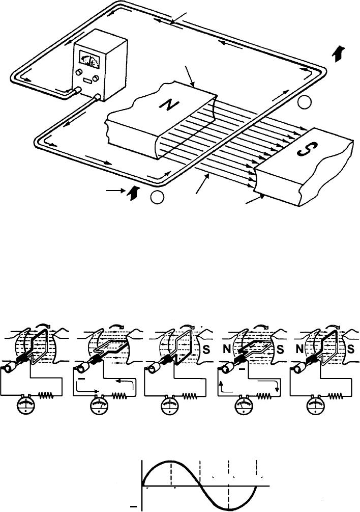
The speed the conductor is moved
In figure 7-23 various angles are shown along with
the induced voltage produced. The armature loop is
The length of the conductor
rotated in a clockwise direction. Its initial or starting
position is shown in part A. (This is considered the
The increase of any of these factors causes the
zero-degree position.) At 0 the armature loop is
induced voltage to increase. Also, remember that the
perpendicular to the magnetic field. The black and
voltage induced is greater when the conductor moves
at right angles to the force lines.
white conductors of the loop are moving parallel to the
N
SN
S N
_
+
+
A
B
C
D
E
+
270
180
360
0
TERMINAL
90
0
VOLTAGE
ASf07023
Figure 7-23.--Output voltage of an elementary generator during one revolution.
7-14