CONTROL POT.
LOAD
20
CIRCUIT
LAMINATED
19
CORE
SHEET STEEL
CONTROL
18
CIRCUIT
WROUGHT IRON
LAMP
17
16
15
AC SOURCE
ASf07017
CAST STEEL
14
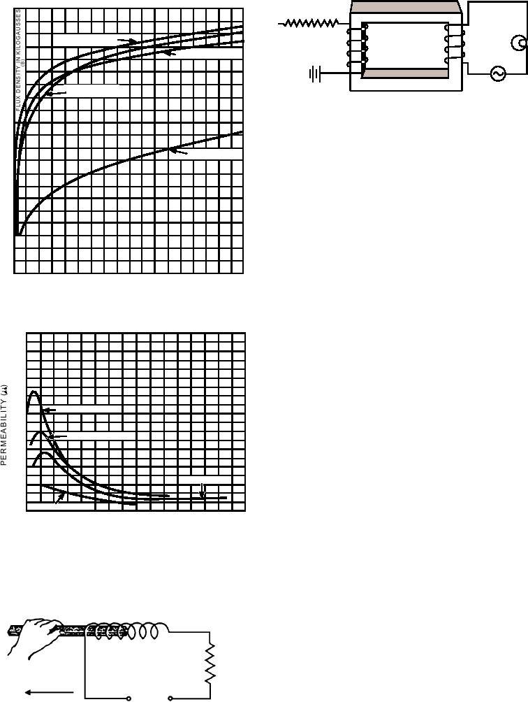
Figure 7-17.--A basic magnetic amplifier.
13
12
the l o a d c u r r e n t i n c r e a s e s , c a u s i n g t h e p ow e r
11
developed in the load to increase.
10
CAST IRON
If control current increases enough to saturate the
9
core completely, the load winding reactance drops
8
nearly to zero. The resistances of the winding and of
7
6
the load are the principal current limiting elements. In
5
this condition, maximum voltage is applied to the load
4
and the lamp glows at maximum brightness.
3
On the other hand, decreasing the control current
2
causes an increase in the reactance of the load winding
1
0
since the operating point is moved toward the steep part
60 70 80 90 100 110 120 130 140 150 160 170 180
40 50
0 10 20 30
of the curve, increasing the permeability. This places
GILBERTS PER CENTIMETER OF LENGTH
(H)
the coil at a maximum value of load current and the
A
minimum load power. Thus, for a small change in
control power, the magnetic action produces a large
4000
3800
change in load power. This action causes the device to
3600
function as an amplifier.
3400
3200
Although the explanation just given illustrates a
3000
2800
basic magnetic amplifier and the method of electrically
2600
controlling permeability, it is seldom used because it is
2400
SHEET STEEL
2200
a very inefficient magnetic amplifier. The problems of
2000
this amplifier are primarily caused by transformer
1800
WROUGHT IRON
1600
action. Transformer action causes energy to be coupled
1400
1200
from one winding to the other. The alternating flux,
1000
which results from load current, induces voltage into
800
CAST STEEL
600
the control winding (refer back to figure 7-17). If the
400
control winding has a large number of turns, the
200
CAST IRON
0
5 10 15 20 25 30 35 40 45 50 55 60 65 70 75 80
induced voltage may become excessive and may even
GILBERTS PER CENTIMETER OF LENGTH
break down the insulation. Even if the coupled voltage
(H)
ASf07015
is small, the control circuit acts as a low-resistance
B
winding and dissipates a considerable amount of
Figure 7-15.--Graph of four magnetic materials--(A)
energy that would normally be applied to the output.
magnetization curves; (B) permeability curves.
Improved Magnetic Amplifier
A more satisfactory circuit arrangement results
when the basic amplifier is modified, as shown in
figure 7-18. This device is often employed for
R
OUTPUT
L
controlling large amounts of alternating current. It
LOAD
contains a three-legged core with an ac winding on
POWER INCREASE
115V A-C
each outer leg and a dc control winding on the center
SUPPLY
leg. The chief advantage of this core structure is that
ASf07016
Figure 7-16.--Varying coil inductance mechanically.
7-10

