current. A combination of the two types can overcome
regulators used in current dc systems are solid-state
electronic units. The voltage regulator governs the
the disadvantages of both. This combination of
generator by sampling the output voltage and
windings is called the compound-wound dc generator.
supplying the proper field excitation to maintain a
COMPOUND-WOUND GENERATORS.--
constant 28-volt dc output. The following paragraphs
Compound-wound generators have a series-field
explain the operation of a typical solid-state regulator.
winding in addition to a shunt-field winding, as shown
Transistorized voltage regulators are rapidly
in view C of figure 7-26. The shunt and series windings
replacing the older systems that use carbon pile and
are wound on the same pole pieces.
magnetic amplifiers. Solid-state regulators are more
When load current increases in the
economical in original cost and repair. They are only a
compound-wound generator, the armature voltage
fraction of the weight of the older units.
decreases just as in the shunt-wound generator. This
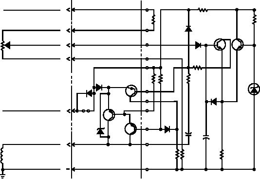
The solid-state regulator, shown in figure 7-27, is a
causes the voltage applied to the shunt-field winding to
very basic system. It is designed to control the field
decrease, which results in a decrease in the magnetic
voltage by using no mechanical components. This
field. This same increase in load current, since it flows
system uses an externally mounted voltage adjusting
through the series winding, causes an increase in the
potentiometer. It is located on the generator instrument
magnetic field produced by that winding.
panel, in full vision of the operator. The voltage
By proportioning the two fields so that the
adjusting potentiometer can be used to increase the
decrease in the shunt field is just compensated by the
generator output, compensating for voltage drops
increase in the series field, the output voltage remains
during load conditions.
constant. As you can see, by proportioning the effects
During normal operation, the voltage adjusting
of the two fields (series and shunt), a
potentiometer is set for 28 volts. The generator output
compound-wound generator provides a constant
voltage is sensed at terminal A. The sensed voltage of
output voltage under varying load conditions. Actual
the generator output is supplied through a voltage
curves are seldom, if ever, as gradual as shown.
divider circuit. The voltage divider circuit includes R1,
the external voltage adjusting potentiometer, and R7.
DC Voltage Regulators
The external voltage adjusting potentiometer is a
variable resistor. The setting of this resistor determines
Dc voltage regulators are used to maintain a
the proportion of the generator voltage that can bias the
constant generator voltage output despite variations in
base of transistor Q4. As the generator output voltage
generator speed and load conditions. The voltage
varies, the bias voltage from the external voltage
+ SENSING
A
FROM GEN.
R8
OUTPUT
R1
R10
CR4
04
05
CR5
JAN
JAN
JAN
B
JAN
1N654
1N654 2N657
2N657
EXTERNAL
VOLTAGE
C
ADJUSTING
POTENTIOMETER
D
R5
VR1
CR1
USN
CR11
USN
03
R4
R3
R2
1N821
USN
1N250B
2N5884
CR7
1N250B
JAN
1N645
01
2N5864
CR7
24VDC +
E
JAN
1N645
VR3
02
JAN
C1 +
2N5884
C2
1N5648A
-
F
FIELD
R6
R9
R7
WINDING
G
ASf07027
Figure 7-27.--Simplified solid-state dc voltage regulator.
7-18

