
adjusting potentiometer also varies. The divided
Rotating-Armature Generators
generator voltage is applied to the base of Q4 and to
capacitor C2. Diode CR5 blocks the capacitor's
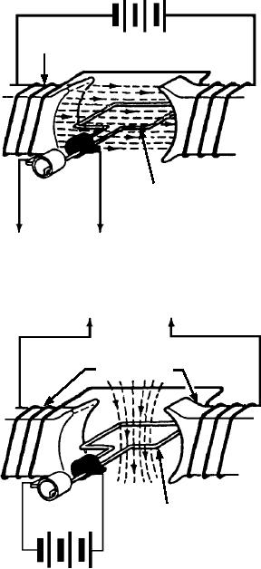
The rotating-armature ac generator (alternator) is
discharge. Q4 regulates the operation of transistor Q3
similar in construction to the dc generator in that the
by varying its base voltage. The degree of conduction
armature rotates in a stationary magnetic field, as
of transistor Q4 is determined by its base voltage and
shown in view A of figure 7-28. In the dc generator, the
the difference in potential between that voltage and the
emf generated in the armature windings is converted
reference voltage across R9. Transistor Q5 and the
from ac to dc by means of the commutator. In the ac
temperature compensated Zener diode VR1 provide
generator, the generated ac is brought to the load
the reference voltage across R9. CR7 links this
unchanged by means of slip rings. The rotating
reference voltage to capacitor C2 and the base of
armature is found only in generators of low power
transistor Q4 when the reference voltage is higher than
rating and generally is not used to supply electric
the sensed input. This limits the emitter to base
power in large quantities.
potential during varying inputs.
Q4 controls the bias of Q3 by varying the base
potential. When Q3 is cut off, maximum battery
voltage is applied to the field winding by Q1 and Q2, a
FIELD
FIELD
Darlington stage amplifier. When Q3 is saturated, a
E X C I TAT I O N
minimum voltage is applied to the field. The battery
voltage is then dropped across the emitter-collector
junction of Q3 and the collector resistor R6.
Now that the function of each major component
has been explained, visualize their actions during a
varying generator output.
A R M AT U R E
As the generator output increases, sensed voltage
applied to the base of Q4 by the voltage divider circuit
also increases. This causes Q4 to conduct more. Q3 is
AC OUTPUT
driven into a higher conducting state. The voltage drop
R O TAT I O N A R M AT U R E A C G E N E R ATO R
across the emitter and collector of Q3 biases the
( A LT E R N ATO R )
Darlington stages Q1 and Q2. The Darlington stage is
A
then less conductive. This decreases the field voltage.
As a result of a weaker field voltage, the generator's
AC OUTPUT
output is decreased. This decreasing action continues
until the sensed voltage is reduced to the Zener
reference potential.
A R M AT U R E
When the generator voltage decreases, the base
voltage of Q4 decreases. Q4 conducts less and causes
Q3 to conduct less. The emitter voltage of Q3 becomes
more positive, causing Q1 and Q2 to be more
conductive. This increases the field voltages and
current until the sensed voltage reaches the Zener
reference potential. This action is repeated many times
each second, providing a seemingly constant generator
FIELD
output.
AC GENERATORS
FIELD
Many of the terms and principles covered in the
E X C I TAT I O N
following paragraphs are familiar to you. They are
basically the same as those covered in the dc generator
R O TAT I O N F I E L D A C G E N E R ATO R
section.
( A LT E R N ATO R )
B
ASf07028
There are two types of ac generators--rotating-
Figure 7-28.--Types of ac generators.
armature and rotating-field.
7-19