
with overcurrent protection. The braking mechanisms
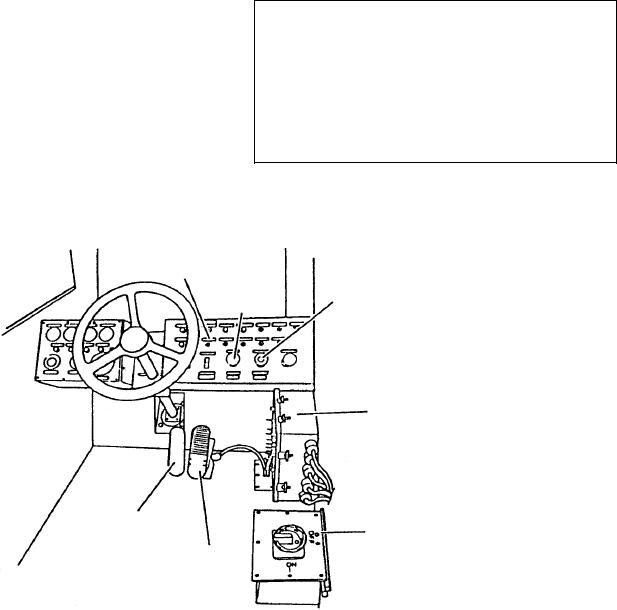
(fig. 13-2), and circuit breakers are located within easy
are activated when speed or movement demands are
reach of the operator. The high cab places the operator
removed. This allows adequate time for motor
in position to view the damaged aircraft and receive
slowdown. The motor drive cabinet receives 440-volt
signals from those on the deck.
ac, 60-Hz, 3-phase power from the ac generator. Then,
The accelerator pedal in the crash crane works
ac and dc power is available from the MDC.
similar to the accelerator pedal in a car. The same is true
of the brake pedal and steering. Both the brakes and
POWER TRAIN
steering are controlled by hydraulic systems.
The two 60 hp, dc-drive motors are identical, but
The crane can be operated from outside the cab
coupled differently. The mid-drive motor is coupled to
from a pendant control box (fig. 13-3) located on the
the differential via a universal joint coupling. The rear
left side of the crane, just aft of the forward wheel
power-train motor is connected to the differential drive
assembly (fig. 13-1). A fiber optic cable connects the
via a coupling. The differential carriers are suspended
pendant box to the crane. When using the pendant
within the structural frame. Unlike the differential in a
control system, the operator walks beside or behind the
tow tractor, however, they carry no radial loads. Instead,
crane, and controls it through the use of toggle
switches. Maximum speed during pendant operation is
they are used to transmit torque to the wheels. The
outputs of the differential carriers are coupled to the
limited to about 1 mile per hour.
planetary wheel drives via couplings connected to
NOTE: To learn more about fiber optic cables,
high-torque universal joint drive shafts.
refer to Navy Electricity and Electronics Training
Series (NEETS), Module 24, Introduction to Fiber
Optics.
WARNING
MOTOR DRIVE CABINET
The dc motors weigh 1,675 pounds each, and
each differential weighs 250 pounds. For this
The motor drive cabinet (MDC) is located on the
reason, removal and replacement must be done
left side and under the cab. The cabinet contains
with great caution. Refer to the technical manual
controls for the hoist, rear drive axle, and mid rear drive
for approved procedures.
axle. The motor drive logic responds to cab and remote
controls protected by various control mechanisms. The
Except for accommodations for its size, an AACC
microprocessor-driven current control provides timing
wheel assembly is removed in the same way that a
and firing commands to assure smooth motor operation
THROTTLE
SWITCH
TRAVEL
DIRECTION
LUFF/HOIST
SWITCH
SWITCH
24 VDC CIRCUIT
BREAKER
PANEL
BRAKE
PEDAL
440 VAC POWER
DISCONNECT SWITCH
ACCELERATOR
PEDAL
ASf13002
Figure 13-2.--Operator's cab.
13-4