tensioner sheave assembly. The sheave assembly
mounted on the tensioner frame guides the cables as
they pass from the sheave and adapter assembly to the
clevis assembly. The lead sheave assemblies guide the
cables between the retraction engine and the grab.
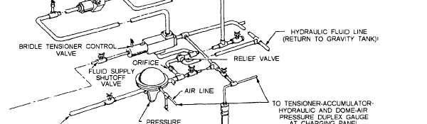
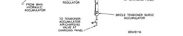
BRIDLE TENSIONING SYSTEM (DECK)
The bridle tensioning system (fig. 4-57) consists of
a bridle tensioner
cylinder,
control
valves,
pressure-reducing valves, accumulators, limit switches,
and associated valves and piping.
NOTE
The Mk 2 nose gear launch unit is an
integral part of the bridle tensioning system. Its
description and operation is discussed later in
this manual.
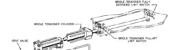
The bridle tensioner cylinder assembly (fig. 4-58)
is mounted in the nose-gear-launch-unit deck housing,
aft of the catapult track. The purpose of the tensioner
cylinder is to exert force on the catapult shuttle, via the
shuttle grab assembly, to tension the aircraft launching
hardware prior to launching.
The piston rod extends into the catapult track, and
a ram support on the forward end of the rod is equipped
with rollers that bear on the catapult track surfaces. A
port on the forward end of the cylinder is pressurized at
all times the bridle tensioner pressure regulator valve is
charged. Fluid flow to the port on the after end of the
cylinder is controlled by the bridle tensioner control
valve.
When the aircraft is tensioned, the bridle tensioner
control valve (fig. 4-57) directs fluid from the pressure
regulator to the aft port of the bridle tensioner cylinder.
This fluid pressure acting on the large surface of the aft
end of the piston causes the grab and shuttle to move
forward. When the control valve is shifted to vent the
aft end of the cylinder to gravity, the constant pressure
on the forward side of the piston moves the piston back
to its FULLY AFT position.
Figure 4-57.—Bridle tensioning system.
4-45