replacing a burned-out fuse, you should be sure that the
new fuse is the same size (capacity in amperes) as the
original.
The circuit breaker serves the same purpose as the
fuse, but it is designed to open the circuit under
overload conditions without injury to itself. Thus, the
circuit breaker can be used again and again after the
overload condition has been corrected.
LIMIT SWITCHES.— Limit switches are used as
remote indicators of the position of various components
throughout the system. They are actuated mechanically
by the movement of the component. Electrical contacts
within the switch change the mechanical action to an
electrical signal indicated by lights on the various
operating panels.
MICROSWITCHES.— Microswitches serve the
same function as limit switches except they are used
where a very limited mechanical movement is required
(1/16 inch or less). While the term Microswitch
suggests the function of the switch, it is nothing more
than the brand name of the particular type of switch.
C-7/C-11 Control Console
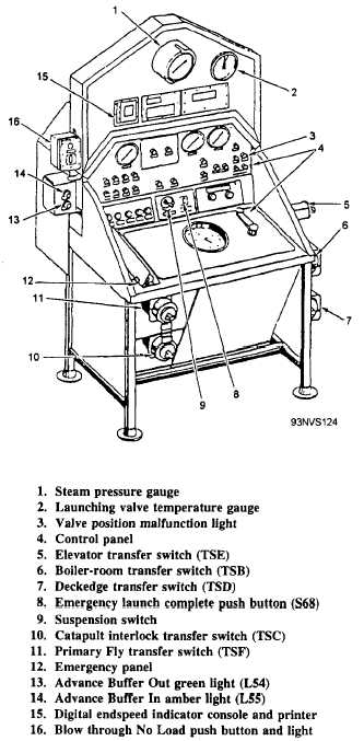
The C-7/C-11 control console (fig. 4-62) is located
below decks in the vicinity of the launch valves and is
the focal point of the catapult electrical control system.
The control panels on the control console contain
various gauges, push buttons, switches, lights, sequence
control handcrank and sequence dial, and CSV controls
(figs. 4-62 and 4-63).
Sequence Control Panel
The sequence control panel in figure 4-64 contains
a handcrank and indicator dial with a cam indicator, a
main-drive indicator, and various gears, shafts, and
cams. The camshafts and the cam control unit are
operated by means of the handcrank.
The crank is mounted on a shaft to which a gear is
attached. This gear meshes with a similar gear mounted
on a shaft 90° from the crankshaft. The second shaft
operates the camshafts by means of universal couplings,
a shaft extension, and additional gears.
One full turn of the crank from the 12 o’clock
position advances the cam-control unit from one
operational phase to the next. (A detent at the 12
o’clock position indicates the proper position of the
handcrank at the completion of each turn.) A
solenoid-operated lock is provided to prevent the crank
from turning past the FINAL READY position until the
catapult
Figure 4-62.—C-7/C-l 1 control console.
has been fired and LAUNCH COMPLETE
attained.
The dial on the sequence panel indicates the
sequence of operation of the catapult. The DK cam
indictor, which is black, and the DC cam main-drive
indicator (red) indicate the position of the two
camshafts in relation to the particular phase of catapult
operation on the indicator dial. The indicator dial,
shown in figure 4-65, is divided into seven positions,
4-49