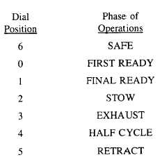
which represent the different phases of operation. The
of operation of the catapult. Figure 4-66 is a schematic
phases are as follows:
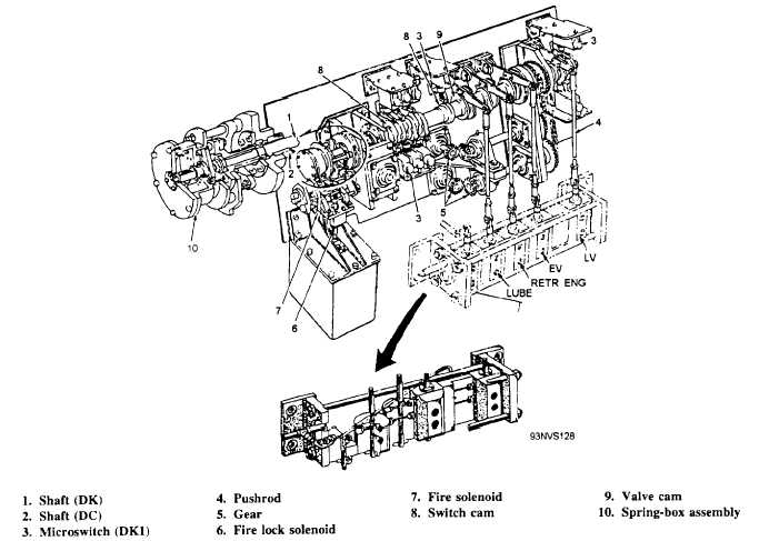
Cam Control Unit
of the cam control unit.
The cam control unit is mounted on a panel in the
back portion of the control console. This unit consists
essentially of two concentric shafts, DC and DK, upon
which a series of cams is arranged. These cams operate
both the cam-operated pilot valves and a series of
microswitches.
The shorter, DC, shaft of the two camshafts is
hollow, enclosing the control portion of the longer, DK,
shaft. Along the length of the DC shaft are arranged
switch-controlling cams and valve-controlling cams.
Mounted above and below the outer camshaft are seven
microswitches, numbered DC 1, 2, 3, 4, 5, 6, and 7,
which are in contact with the switch cams. Also
mounted by brackets are cam follower assemblies. One
end of the cam follower arm pivots in a bracket and the
other end actuates the cam-operated pilot valves by
The cam control unit integrates the functions of the
means of pushrods. Three pilot valves are actuated in
electrical and hydraulic systems and fixes the sequence
this manner. They are the lube (LUBE), exhaust (EV),
Figure 4-66.—Cam control unit.
4-52