operating principles remain the same. The major
difference lies in the console configuration itself. Figure
4-71 is a breakdown of the console into its individual
panels. The following paragraphs contain a brief
description of the panels.
MONITOR PANEL.— The monitor panel consists
of a series of status and malfunction lights. During
normal operation the green status lights are on. If a
malfunction occurs, the green lights will go out and red
lights will come on. The malfunction lights will indicate
red only when a malfunction occurs; there is no
indication from them during normal operation. The
cylinder elongation readout, an 8-day, 24-hour-dial
aircraft clock, and the launching-valve stroke-timer
indicators, light-switch units, and fuses are also on the
monitor panel,
OPERATING PANEL.— The operating panel is
the part of the control console that is used in
conjunction with the deckedge control panel to direct
launching operations. On the panel are light-switch
units for phases of catapult operation. As each phase is
reached, that particular light comes on. The capacity-
selector-valve command and position readouts and
controls are also included on this panel. FIRST READY
and FINAL READY switches are the only ones on this
panel used during normal operation. The remaining
switches are used in controlling the catapult in case of
emergency.
STEAM CHARGING PANEL.— There are three
gauges on the steam charging panel. These gauges
indicate steam pressure, steam temperature, and water
temperature. Lights on the panel indicate the status of
the steam system components and the operational
readiness of the steam pressure and water level.
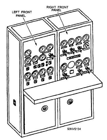
CHARGING PANEL.— The charging panel,
shown in figure 4-72, is used to control and monitor the
hydraulic and pneumatic systems. It also contains
pressure switches. The charging panel is made up of
two panels: the left front panel and the right front
panel.
Left Front Panel.— The left front panel controls
and monitors the hydraulic system. The panel contains
pressure gauges and OFF-ON switches for the main
hydraulic pumps, the auxiliary pump, the circulating
pump, and the lubrication pump. Also included are a
gravity-tank fluid temperature gauge, three accumulator
hydraulic pressure gauges, an off-on pump delivery
control switch, a retraction-engine suspend switch, a
Figure 4-72.—Charging panel.
blowdown valve for the retraction-engine
fluid, and fuses.
hydraulic
Right Front Panel.— The right front panel controls
and monitors the pneumatic system. The panel contains
pressure gauges and controls the accumulator air, air
flask, bridle-tensioner pressure regulator, medium-
pressure air supply, cable tensioner, and low-pressure
air supply. Lights on the panel indicate pressure and
temperature limits for various catapult functions.
TRANSFER SWITCHES (ALL CATAPULTS)
Transfer switches on the side of the control console
are used to transfer various functions from the deckedge
control, primary fly, deck auxiliary, and boiler-room
panels to the control console during emergency
conditions. A catapult interlock (release) switch is used
to release the interlock between adjacent catapults.
DECKEDGE CONTROL PANEL
The deckedge control panel is located on the
catwalk at the edge of the flight deck. The deckedge
control panel is used in conjunction with the control
4-57