steam pressure. Other lights on the panel indicate the
status of the steam system components and the
operational readiness of the steam pressure and water
level. The lower monitor panel consists of lights, light-
switch units, and the capacity-selector-valve position
readout. Lights and light-switch units on the panel
indicate the condition of the catapult throughout the
launching sequence. Light-switch units are also used to
perform various catapult functions during operations.
Emergency Deckedge Control Panel
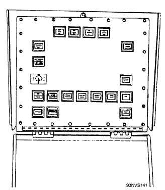
The emergency deckedge control panel (fig. 4-79)
is located on the catwalk at the edge of the flight deck.
This deckedge control panel is only used when
operating in the EMERGENCY MODE I situation. In
this situation, control functions are transferred from the
ICCS to the emergency deckedge control panel and
central charging panel, and the catapult officer directs
operations on deck. The panel contains lights and
light-switch units for phases of catapult operation, the
nose-gear-launchlbridle-arrester selector switch, the
capacity-selector-valve position readout, command
switches, and control switches.
Military Power Lights and Combat Power Lights
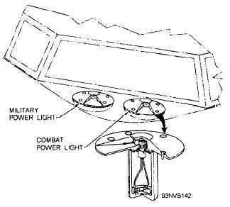
Military-power and combat-power lights (fig. 4-80)
are located on the deck. The lights are installed so they
Figure 4-79.—Emergency deckedge control panel.
Figure 4-80.—Military and combat power lights (typical).
can be seen by the pilot of the aircraft being launched.
During the launching sequence, the lights signal the
pilot to increase the throttle to the appropriate power
setting. The lights are identical except for the lens
color; the military-power-light lens is green, and the
combat-power-light lens is amber.
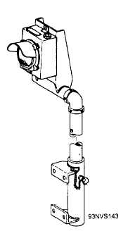
Deck Catapult-Suspend Light
The deck catapult-suspend light (fig. 4-81 ) is
located on the edge of the flight deck. The light flashes
red during a suspend situation to indicate to personnel
on deck that a catapult-suspend situation exists.
Figure 4-81.—Deck catapult-suspend light.
4-61


