console to direct the catapult through a normal
launching cycle. Under emergency conditions, the
functions of the deckedge control panel are transferred
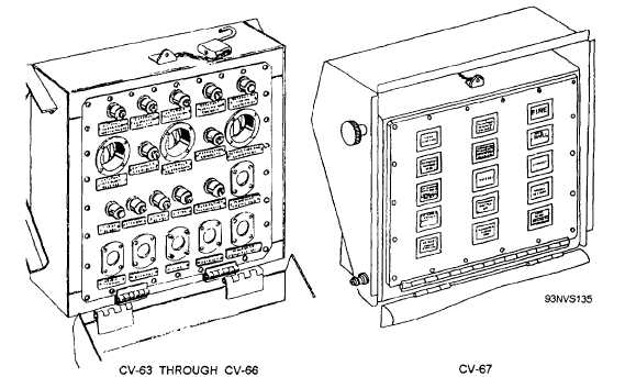
to the control console. Figures 4-73 and 4-74 illustrate
the different types of deckedge control panels,
AUXILIARY DECKEDGE PANEL
(SIGNAL BOX)
In figure 4-75, the auxiliary deckedge panel is
located on the edge of the flight deck, adjacent to the
deckedge control panel. Its function is to indicate the
status of the catapult readiness to the catapult officer.
PRI-FLY (PRIMARY FLIGHT) CONTROL
PANEL
Lights on the Pri-Fly control panel, located in the
air officer’s control center, indicate the readiness
condition of the catapult. A switch on the panel allows
firing of the catapult to be suspended from the control
center in an emergency.
WATER-BRAKE CONTROL PANEL
(C-13 ONLY)
The water-brake control panel, shown in figure
4-76, is located at the water-brakes station. In the event
of an emergency or a malfunction of the water brakes,
a switch on the panel is thrown to suspend catapult
operations.
INTEGRATED CATAPULT CONTROL SYSTEM
(ICCS) CVN-68 AND SUBSEQUENT CARRIERS
The controls for the ICCS are mainly divided
between the ICCS at the deck and the central charging
panel below deck. The ICCS is an enclosure that may
be retracted into the deck when not in use. It contains
the catapult-officer control console and the monitor
control console, and controls the operation of two
adjacent catapults. Sound-powered phones and a system
of indicator lights link the ICCS to the remote panels
for individual catapults. In an emergency, the functions
of the ICCS can be transferred to the emergency
deckedge control panel or the central charging panel,
and the catapult officer can direct operations on deck.
Catapult-Officer Control Console
The catapult-officer control console (fig. 4-77) is
used in conjunction with the monitor control console
and the central charging panel to direct catapult
operations.
The control console is of wraparound design for
ease of operation. Separate operating panels for the two
catapults controlled by the console are located on the
side closer to the applicable catapult. The operating
panels contain status lights, light-switch units for phases
of catapult operation, the nose-gear-launch switch, the
manual-aircraft-data-input-system readouts and erase
switches,
and the capacity-selector-valve position
Figure 4-73.—C-13 deckedge control panels.
4-58