and retraction engine pilot (RETR. ENG) valves (fig.
4-66).
The outer shaft is turned through a system of bevel
gears and universal joints when the crank on the
sequence control panel is turned. A rod, which is also
turned with additional gears and universal joints,
actuates the main-drive indicator on the sequence
control panel.
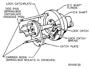
Figure 4-67.—Cam control unit spring-box carrier rods and
dog pins.
The exposed portion of the inner shaft (DK)
actuates a microswitch (DK 1 ) and the launch valve
pilot valve (fig. 4-66). The spring box assembly, the
three carrier rods of the DC shaft, and the three dog
pins of the DK shaft (fig. 4-67) cause the DC and DK
shafts to turn together until the FIRST READY position
is reached. As the shafts turn, their cams, by virtue of
their shapes and position, actuate the microswitches and
cam-operated pilot valves in their proper sequences.
When the FIRST READY position is reached, the
fire lock solenoid is energized, causing the lock
catchplate (fig. 6-67) to engage the rocker-arm roller
(fig. 4-68) and lock the DK shaft in the FIRST READY
position. As the DC shaft rotates into FINAL READY,
the DK shaft is placed under spring tension.
By energizing the firing solenoid [(7) in fig. 4-66],
the DK shaft is released; being under spring tension, it
rotates into position with the DC shaft, actuating the
LV pilot valve. Both shafts then rotate together for the
rest of the operation sequence.
Cam-Operated Pilot Valves
The four cam-operated pilot valves, which operate
the lubrication control valve, retraction-engine control
v a l v e , e x h a u s t - v a l v e c o n t r o l , a n d t h e
Figure 4-68.—Cam control unit rocker-arm operation.
4-53


