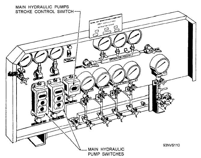
The C-13 linear retraction system also incorporates
a central charging and gauge panel (fig. 4-48). It
contains the pump controls, pressure gauges for the
various engine components, a retraction engine suspend
switch, and an air charging/blowdown manifold with
the associated valves and piping.
ROTARY RETRACTION ENGINE
The rotary retraction engine (fig. 4-49) consists of
a hydraulic motor, which transfers its motion by means
of a drum assembly to the cable drive system, Advance
of the grab is accomplished by admitting pressurized
fluid to the hydraulic motor. This causes the motor and
drum to rotate, winding the grab advance cables onto
the drum while paying out the grab retract cables. The
rotation of the cable drum is stopped by fluid braking
of the hydraulic motor. Retraction is accomplished by
admitting pressurized fluid to the hydraulic motor so
that the flow of fluid is opposite of what it was during
advance. This reverses the rotation of the motor and the
drum, causing the retract cables to be wound onto the
drum while the advance cables are payed out off of the
drum. The retract motion is also stopped by fluid
braking of the hydraulic motor. Electrical limit switches
and hydraulic valves mounted on the upper engine
framework are actuated by cams on the top of the
traverse carriage assembly, and control the operation of
the engine.
The hydraulic motor (fig. 4-49) is rotated by
pressurized fluid from the main hydraulic accumulator.
Speed and direction of rotation are controlled by
various directional valves located on the retraction
engine. The hydraulic motor is coupled directly to the
drum assembly, causing the drum to rotate in the same
direction and speed as the motor.
Figure 4-48.—Central charging panel (C-13).
4-38


