inside the drive housing and the other end is outside.
The inside end is geared to the worm wheel gear;
therefore, when the direct drive assembly rotates, the
speed counter shaft rotates. The speed counter, but,
rotates at a much slower rate because of the gear
ratio. The outside end of the speed counter shaft is
covered by an attached cap. The cap has a raised
bump on one side of its top. Bowl speed is determined
by the operator who places his finger on the outer
edge of the cap and then counts the number of times
the raised bump touches his finger in 1 minute.
During full bowl rpm, the count should be between
146 and 150 times per minute.
Because of the gear ratio, the drive motor rotates
at 1,770 rpm, the bowl rotates at 4,100 rpm, and the
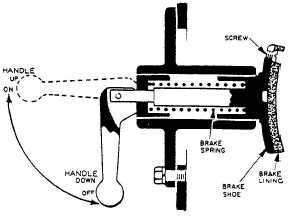
speed counter rotates at 146 to 150 rpm. A handbrake
(fig. 4-32) is provided to stop the purifier. This brake
is for emergency use only. It consists of a spring-
loaded brakeshoe and an eccentric handle. The
brakeshoe has a replaceable section of bonded brake
lining. When the handle is down, the brake is off.
When the handle is raised to the up position, the
brake is on. In the on position, the spring forces the
brakeshoe and lining against the outer surface of the
brake drum. Friction, thus created, causes the
purifier to come to a stop.
In the base of the drive housing is an oil sump
for the oil lubrication system (fig. 4-33). All the
bearings on the spindle and drive shaft are lubricated
by this oil. The drive housing is divided into two
compartments. One of these compartments contains
the direct drive assembly coupling and the other
contains the gears and bearings that are lubricated
by oil. A metal partition separates the two
compartments. The direct drive shaft passes through
this partition and a gasket is installed around the
shaft to prevent oil from entering the direct drive
coupling compartment. The worm wheel gear on the
drive shaft is partially submerged in the oil. Rotation
of this gear splashes the oil about within the oil
Figure 4-32.—Brake assembly.
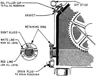
Figure 4-33.—Oil lubrication system.
lubrication compartment, thus supplying oil to the
bearings and gears. The oil sump holds from 8 to 8
1/2 quarts of grade 90 gear oil. Proper oil level is
determined by a circular sight glass on the side of the
drive housing. The glass retaining ring has two
inscribed lines to indicate proper oil level. The white,
top line, is the high or full oil level. The red, bottom
line, is the low oil level mark.
On some installations where the oil sight glass
could not be seen easily in its normal position, the
sight glass has been extended out and turned to give
a clear view to the operator, or a dip stick has been
added to the oil filler cap. The dip stick has two
marks. The lower mark indicates lubricating oil
should be added. Fill to the upper mark. To check the
oil level, pull the stick completely out through the
cap. Wipe with a clean, dry rag. Push the stick all the
way in through the cap and pull it out again to read.
Be sure the stick always rests on the cap.
An oil fill cap is located near the top of the drive
housing. An oil drain plug is at the base of the oil
sump.
Bowl Shell Assembly
The bowl shell assembly (fig. 4-34) provides the
working area for separation of contaminants from JP-
5. The entire bowl shell assembly sits on top of the
spindle assembly. The spindle assembly causes the
bowl shell assembly to rotate. This rotation is
transmitted to the fuel, thus providing the necessary
centrifugal force to cause separation to take place.
During operation, the bowl shell assembly contains a
fresh water seal to prevent loss of the JP-5. Most of
the separated solids and emulsions are retained
within the bowl shell assembly, but are completely
removed from the line of flow of the liquids.
4-38