The air escape riser (vent line) prevents a
buildup of pressure when the tanks are being filled
and prevents a vacuum from forming when the tanks
are being emptied.
There are usually four air escape mains serving
the forward and after groups of tanks: two forward
(one port and one starboard) and two aft (one port
and one starboard). A cane-shaped vent line extends
up from each main to just below the 02 level and
loops back down to just below the 01 level, where it
terminates in scan. One end of the can, which
contains a flame arrester, penetrates the skin of the
ship and is open to the atmosphere. The outboard end
is covered with a ratproof screen, and the inboard end
is closed by an inspection plate. The flame arrester is
cleaned quarterly.
CAUTION
The ship’s side cleaners should be cautioned
about spray painting near these vents. Sprayed
paint can stop the flow of air through the vents
by clogging the flame arrester.
An overflow line extends from near the top of the
storage tank to an overflow tank. This line is
considerably larger than the tank fill line to prevent
rupture of the storage tank in the event of overfilling
at high pressure. When the tank is full, it will
overflow via a one-way check valve into the overflow
tank for that nest of tanks.
NOTE
A nest of tanks is that small unit of tanks
within a group of tanks that is serviced by one
overflow tank. The forward and after groups of
storage tanks consist of several nests of tanks.
A bolted manhole cover provides access to the
tank for inspection, cleaning, and maintenance. A
sounding tube extends from the extreme bottom of
the tank to the second or third deck. The lower end is
secured to a striker plate, and the upper end is closed
by a threaded access cap. That section of the
sounding tube within the tank has evenly spaced
holes to ensure that the level of fuel in the tube is the
same as that in the tank. Sounding tubes are
provided for measuring the quantity of JP-5 in the
tank, detecting water, and thieving a sample.
The suction and fill tailpipe extends from the
manifold to terminate between 6 to 24 inches off the
bottom at the lowest end of the tank. A nonvortex
bellmouthed fitting and a splash plate are installed
on the end of the tailpipe. This fitting reduces
turbulence when filling, prevents a vortex from
forming when emptying the tank, and prevents
taking a suction directly off the bottom. Storage tanks
are filled and emptied through this line.
The stripping tailpipe is similar in design to the
suction and fill tailpipe except it is smaller and has
no splash plate. This line extends from the stripping
manifold to a maximum of 1 1/2 inches off the bottom
at the lowest end of the tank. The stripping tailpipe is
used to remove water and sludge from the bottom of
the tank and to completely empty the tank by
removing the last 24 inches of usable JP-5 when
consolidating the fuel load. The stripping tailpipe is
also used when ballasting and deballasting the
storage tanks.
NOTE
JP-5 storage tanks have a filling rate of 500
gpm per tank, with the required minimum of
six tanks on the line.
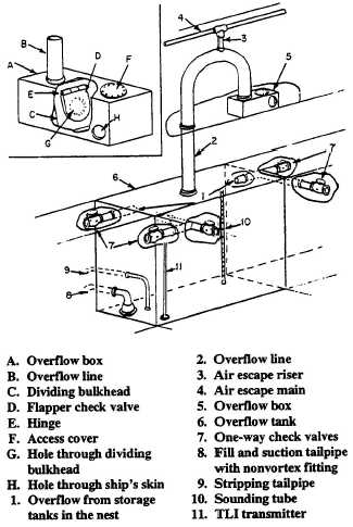
JP-5 Overflow Tanks
Overflow tanks (fig. 4-42) have the same fittings
previously described for the storage tanks, except for
Figure 4-42.—Typical JP-5 overflow tank.
4-51