the large overflow line and the arrangement of the
vent line. In addition to serving as a regular storage
tank, they are also designed to receive the overflow
from the other storage tanks in their respective nest.
The overflow tanks are actually a safety feature
to prevent rupturing of storage tanks if they are over-
pressurized during a filling operation. The overflow
tanks overflow overboard when they are full. The
large overflow line extends up from the top of the
tank to just below the second deck. Here it loops back
down and discharges into an overflow box on the
third deck. The overflow box contains a flapper check
valve that allows JP-5 to be discharged overboard but
prevents seawater from entering the tanks. An
inspection plate located directly over the valve allows
access for cleaning and maintenance. In the past,
flapper check valves have frozen open due to
corrosion, and seawater contamination of JP-5 has
resulted. These valves must. therefore, be inspected
at least every 6 months (more often if necessary).
The overflow tanks are vented via an air escape
riser from the top of the loop in the overflow line to
one of the common air escape mains. Overflow tanks
are the last tanks to be filled when receiving JP-5
aboard and are the first tanks to be emptied when
transferring internally.
Contaminated-JP-5
Settling Tanks
The contaminated-JP-5 settling tanks are
designated tanks that receive JP-5 from hose
flushings, defuels, tank stripping operations, and the
initial flow during a refueling at sea. In addition to
standard piping, these tanks have piping branching
from the defuel mains. Each branch of defuel piping
going into a contaminated settling tank must
terminate about 48 inches above the bottom of the
tank, with a perforated horizontal run about 24
inches long to reduce turbulence.
After stripping, JP-5 transferred from these
tanks will be transferred via a JP-5 reclamation
prefilter and JP-5 reclamation filter/separator, in that
order, to the storage tank manifold of the selected
storage tank to be filled.
JP-5 Service Tanks
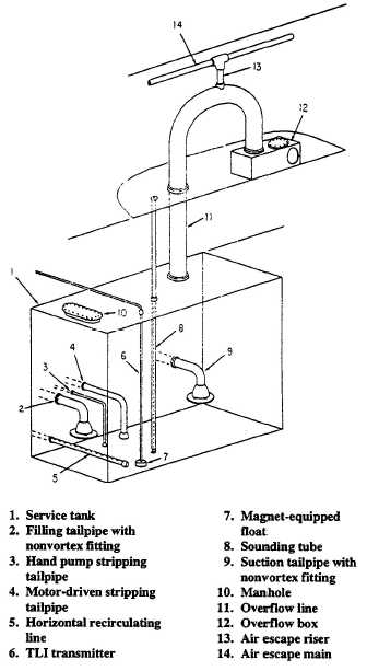
Although much of the equipment in the service
tanks (fig. 4-43) is similar to that described in the
storage and overflow tanks, the piping arrangement
is different and additional equipment is required.
Figure 4-43.—Typical JP-5 service tank.
Service tanks have an independent filling
tailpipe and an independent suction tailpipe. The
filling tailpipe branches from the service tank fill line
header in the JP-5 pump room to terminate in a non-
vortex bellmouth fitting between 6 to 24-inches off
the tank bottom. Additionally, the termination height
will beat least 3 inches lower than the suction
tailpipe. Service tanks are NEVER filled directly from
a tanker, barge, or pier. They are always filled from
settled storage tanks, via the centrifugal purifiers.
The suction tailpipe extends from the service
pumps common suction header to terminate in a non-
vortex bellmouth fitting either 12 or 24-inches off the
tank bottom in the opposite end from the fill line.
4-52


