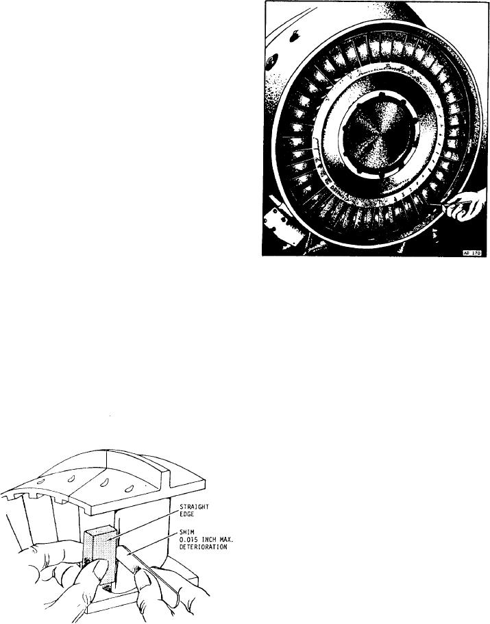
inspect the vanes for signs of bowing. Replace
bowed vanes that are in excess of the allowable
clearance with vanes of the same classification.
Use a straightedge and feeler gauge stock to
measure bowing. See figure 10-15. Damage that
does not crack the metal or reduce the vane
thickness by more than allowed is acceptable
without rework. This is true if the damage is of
a gradual contour shape and not sharp or
V-shaped. Round bottom dents on the leading
edge may be acceptable without rework. Dents
must not exceed allowable limits in depth and
must not crack or tear the vane. Blend sharp
indentations to remove stress concentration.
Determine how many vanes you need to
replace on the particular engine before you
measure the nozzle guide vane area. If the
replaced blades exceed the allowed number and
you must measure the area, it is better to replace
the assembly.
One of the final procedures in the maintenance
of the turbine section of a turbojet engine is to
check for clearances. The service instructions
manual gives the procedures and tolerances for
checking the turbine. Figures 10-16 and 10-17
Figure 10-16.-Measuring the turbine blade to shroud tip
show clearances being measured at various
clearance.
locations. Use special manufacturer's tools to
obtain accurate readings. Also, use the tools
section thoroughly, along with the combustion
described in the service instructions manual for
specific engines.
section and turbine section of the engine. The
exhaust section of an afterburning engine is
subject to extreme heat and pressures. Inspect the
EXHAUST SECTION INSPECTION
external area of the exhaust cone and tail pipe for
cracks, warping, buckling, and hot spots. Hot
The exhaust section of the turbojet engine is
spots on the tail cone are a good indication that
very susceptible to heat cracking. Inspect this
a fuel nozzle or combustion chamber is not
functioning properly. If there is an afterburner,
inspect the afterburner flap segments for burn-
ing, warping, or misalignment. Figure 10-18
shows an afterburner duct and nozzle assembly
with flap segments closed. Inspect the afterburner
synchronizing gear segments for worn and missing
teeth and security of installation. Inspect the
nozzle actuation pistons for cracks and/or bent,
chafed, or scored piston rods. Inspect the roller
guides for warpage and the turnbuckle for security
of installation.
Inspect the internal area of the exhaust pipe
and afterburner for evidence of hot streaks,
buckling, and warping, including the flame
holder. Also, inspect all external fuel and
hydraulic lines for evidence of distortion,
buckling, or leakage. Accomplish the repair and
replacement of parts of the exhaust section using
Figure 10-15.-Checking vane bowing.
10-18

