
furnishes a permanent record of test results. Two
magnetic tape transports provide rapid access to
avionics test programs and immediate availability
of VAST self-check programs.
The data transfer unit (DTU) (fig. 2-41) serves
as the operator-machine interface. It synchronizes
instructions and data flow between the computer
and the functional building blocks. The DTU also
contains the display and control panels.
The DTU control panel lets the operator
communicate with the computer. You will also
communicate with the stimulus and measurement
section of VAST by a keyboard and mode select
key. You can operate the test station in manual,
semiautomatic, or fully automatic modes.
The DTU contains a maintenance panel
that monitors station auto-check results and
shows building-block faults. Transmission of
instructions from the control computer is on a
request/acknowledge basis. Essentially, the
response rate is controlled by the stimulus and
measurement systems. This lets you transmit
instructions at an asynchronous rate correspond-
ing to the maximum frequency at which a given
building block or avionics unit can respond. There
is no requirement for immediate program storage
in the DTU.
VAST STATION
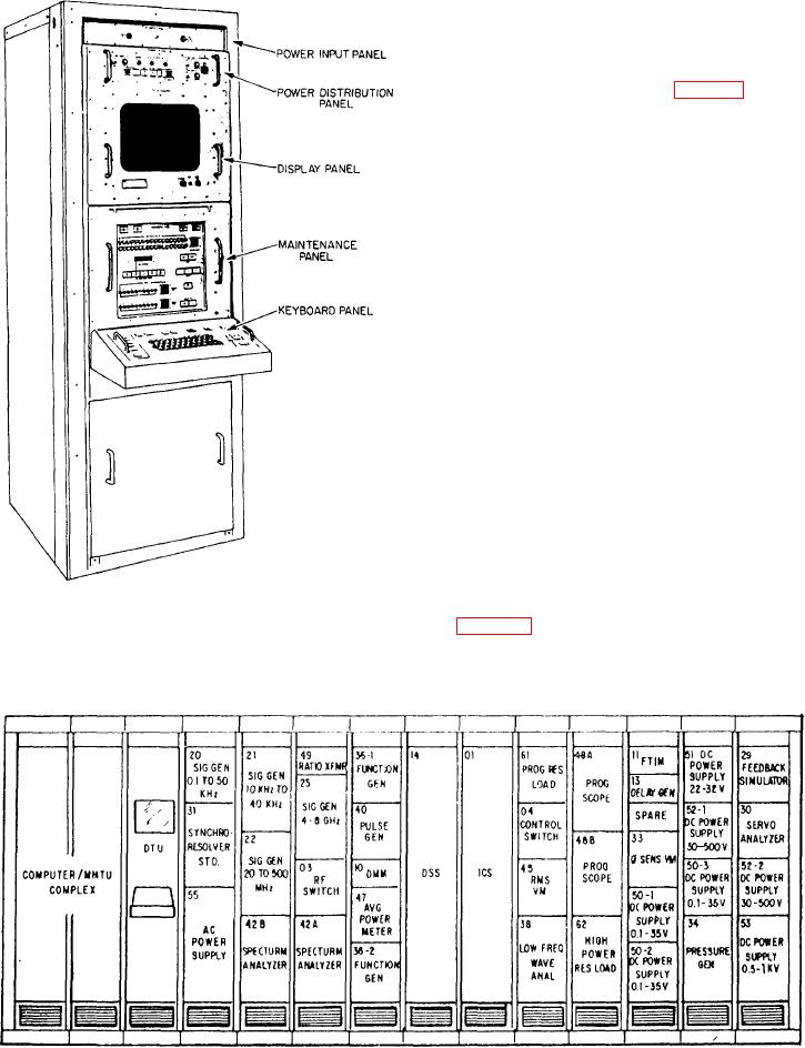
A VAST station may have as many as 14 racks
of stimulus and measurement building blocks.
Figure 2-41.-Data transfer unit (DTU).
(See fig. 2-42.) Large station configurations may
contain as many as 17 core building blocks.
Figure 2-42.-VAST station with building blocks.