
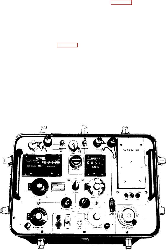
front panel of the test set. All the components are
of input settings and error amplification of
on the underside of the control panel. This
incremental gain comparison. It also avoids
makes the subassemblies and components easily
the chance of error in calculating the gain
accessible when the panel is not in it's carrying
factor.
case. The test set simulates airspeed and altitude
information, which is displayed on the front
For complete instructions on this tester, you
panel. See table 2-6 for test set particulars.
should refer to the current Operation and Service
Instruction Manual, NA 17-15CFA-2.
The test set has the following five capabilities:
1. It performs overall system checks on the
following equipment, pneumatic systems, air data
PRESSURE-TEMPERATURE TEST
systems, flight instruments, and pneumatic
SET TTU-205C/E
ancillary equipment. This equipment may be
either installed in or removed from the air-
The pressure-temperature test set (fig. 2-36)
craft.
provides regulated pitot and static pressure for
checking performance characteristics of aircraft
2. It provides simulated total temperature for
pneumatic instruments, air data systems, and
the USAF MA-1 Probe, a platinum resistance
other auxiliary equipment. You can also conduct
sensing element whose resistance is 50.0 ohms at
dynamic tests, quantitative calibration tests,
0C.
pneumatic-system leak tests, and total tempera-
ture probe tests using this tester.
3. It connects directly into the aircraft's
pneumatic system to measure and control static
The TTU-205C/E is a compact assembly. It
pressure (Ps) and pitot pressure (PT).
consists of a control panel, components assembly,
and combination carrying case with removable
4. It accepts electrical power from an external
cover. All the controls, indicators, switches,
source.
electrical, and pneumatic connectors are on the
Figure 2-36.-Test Set, TTU-205C/E.