
engine, and immediately take corrective action
when an abnormal condition occurs. Performance
of precision work is necessary when maintaining
fire warning systems to ensure their reliability. An
undetected fire may cost the lives of the aircrew
and possibly millions of dollars in aircraft and
equipment.
In multiengined aircraft, a fire warning usually
dictates that the engine be shut down and the fire
extinguished. The least that can happen if there
is an erroneous fire warning is the aircraft will
abort its assigned mission.
WARNING SYSTEM
The engine fire detector system is an electrical
FIRE WARNING AND
system for detecting the presence of fire or dan-
EXTINGUISHING SYSTEMS
gerously high temperatures in the engine(s) areas.
The system for each engine consists of a control
Learning Objective: Recognize operating
unit, test relay, signal lamp, test switch, and
conditions and characteristics of aircraft
several sensing elements. The detect or uses a
engine fire warning and extinguishing
continuous strip of temperature-sensing elements
systems.
to cover the paths of airflow in the engine com-
Some
turbine engines operate at temperatures
partment. The same engine fire warning systems
of more
than 1,000C. Fuel and oil lines run
are in multiengined aircraft, one for each engine.
with in a
few inches of these extreme temperatures.
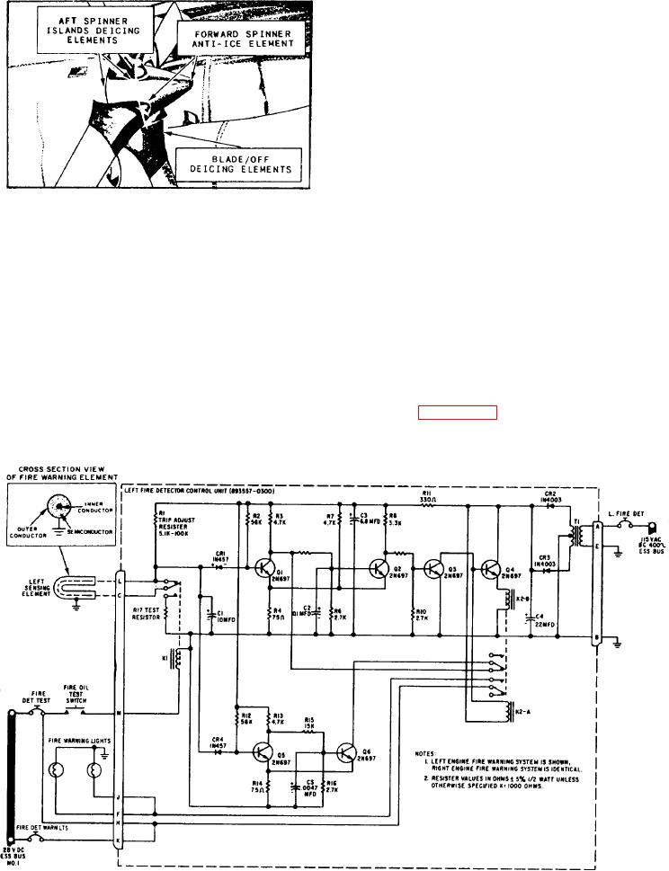
Look at figure 5-12. It shows the electrical
For this
reason, you must closely monitor the
schematic for a fire warning system that is
Figure 5-12.-Typical engine fire warning circuit schematic.