
THROTTLE LEVER ANTICIPATION. --
capacitor charges up to a more positive voltage
value. This results in a current from pin 7 to pin
Any power lever movement (fig. 5-19) causes
8 in signal winding number 1 of the magnetic
a change in dc voltage at the anticipation
modulator. A lagging voltage surge appears in the
potentiometer wiper, which serves as a voltage
servomotor control winding, causing counter-
divider for the RC circuit. The charging voltage
for the capacitor is directly proportional to the
clockwise rotation. This rotation resets the
mechanical governor towards decrease pitch to
position of the power lever. The change in charge
compensate for the reduced power setting. As the
on the capacitor is directly proportional to the rate
servomotor rotates, the feedback potentiometer
at which the power lever moves. If the power lever
movement is to decrease engine power, the
begins canceling the error signal by causing a
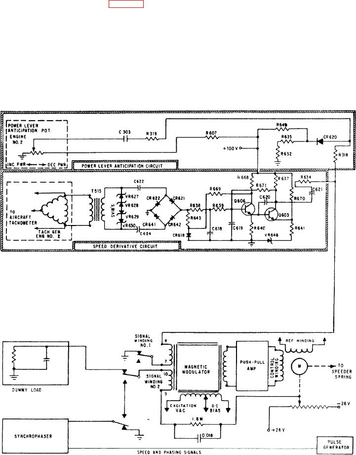
Figure 5-19.-Power lever anticipation and speed derivative circuits in normal governing mode.
5-34