
propeller blade angle errors. (Figure 5-20 shows one
error circuits receive no signal. With the sawtooth in
channel of the synchrophasing circuit.)
the positive region, tube V205 conducts. The
The following paragraphs describe phase and
corresponding voltage changes go to the grid of phase
speed error sensing.
difference tube V206A.
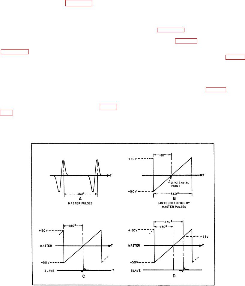
You can see the nature of the sampling action by
referring to figure 5-21. The time interval between
SAWTOOTH FORMER.--The pulse from the
master pulses is the time interval for 360 degrees of
master pulse generator is transformer-coupled to the
propeller rotation (fig. 5-21, view A). The time interval
sawtooth former. The slave pulse generators are
of the sawtooth, which the master pulse generates, is
transformer-coupled to the channel sampler circuits.
360 degrees. The half-time interval, or 180-degree
Figure 5-21, views A and B, shows the master pulse
position, is the sawtooth zero potential point (fig. 5-21,
and the resultant sawtooth formed in the sawtooth
view C). When the slave pulse occurs at the zero point,
former.
the propellers are on phase with a 180-degree phase
difference between them. All references to slave
SAMPLING CIRCUITS.--Pulses from the three
pulses are with respect to the 360-degree interval. The
slave engines couple to the grids of the sampling
point of occurrence of the slave pulse determines the
circuit tubes, while the sawtooth voltage goes to the
signal size in the sampler circuit (fig. 5-21, view D).
plate of one tube and the cathode of the other tube in
This signal represents the phase difference between
all sampling circuits. The positive-going portion of the
propellers.
slave pulse places the tubes in a conductive state.
(Sampling is the same in all channels.) Refer to figure
NOTE: Since the propellers are four-bladed, the
5-20. If the sawtooth is at zero potential when the
relative blade position between the master and slave
slave pulse occurs, neither tube conducts, so the phase
propellers is exactly the same when the slave
difference
and
speed
Figure 5-21.--Master and slave pulse comparisons.
5-37