
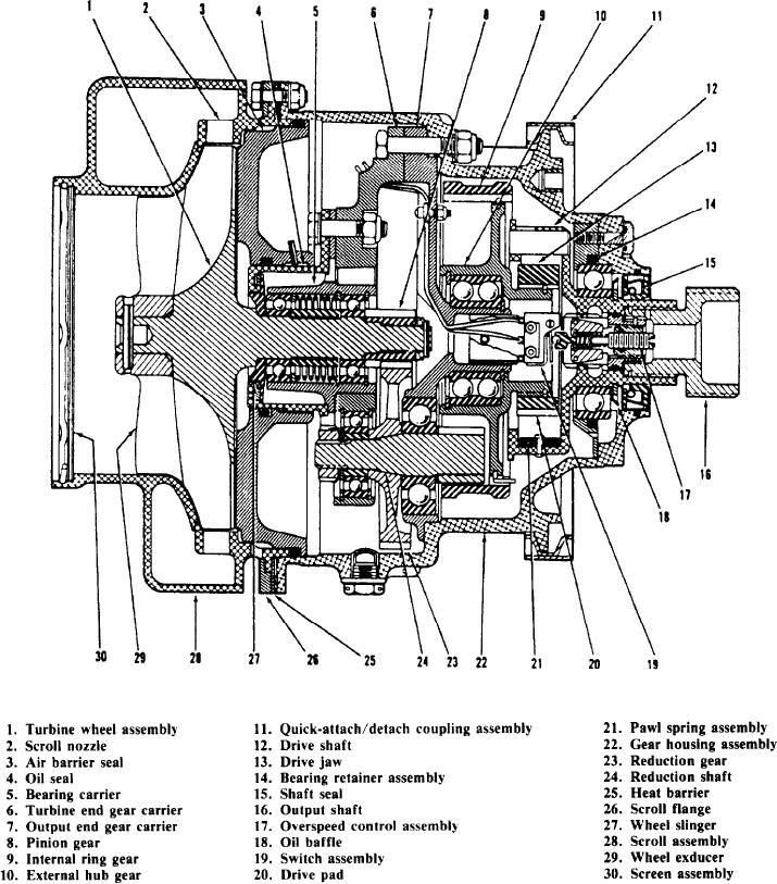
Figure 5-2.-Air turbine starter.
or until the closed overspeed control removes the
holding relay receives a positive potential through
negative potential.
the normally closed external stop switch. The relay
When high-pressure air is at the normally closed
also receives a negative potential through the
regulating valve inlet and the start switch energizes
closed overspeed control provided within the
the holding relay, the regulating valve opens.
starter. The relay continues to hold until the
Thus, admitting compressed air to the starter. The
external stop switch removes the positive potential
5-3