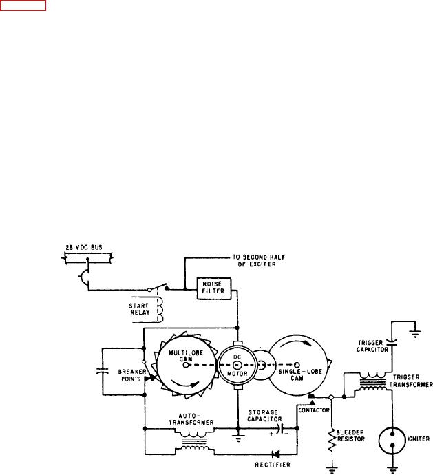
The ignition system gets its input power from
triggering transformer increases the output voltage
the low-voltage dc power supply of the aircraft
of the ignition unit and ensures reliability of the
electrical system. Its function is to produce high
system.
The igniter spark rate varies in proportion to
energy, capacitance-type sparks at the spark
igniters in the engine.
the voltage of the dc power supply, which affects
Input power from the low-voltage supply
the speed of the motor. However, as the same
connects through a noise filter to a dc motor. The
shaft operates both cams, the storage capacitor
motor drives a multilobe cam that operates two
always accumulates its energy from the same
breakers, and a single-lobe cam that operates two
number of pulses before discharge.
contractors. One breaker and one contactor
associate with each side of the system. The two
sides are identical. The following description
applies to either side.
CAUTION
When the multilobe cam closes the breaker
(fig. 5-5), input current flows through the
Due to the high voltage and amperage of
autotransformer's primary winding, establishing
this system, you should use extreme
a magnetic field. Then the breaker opens, the flow
caution around the equipment.
of current stops, and the field collapse induces
about 1,000 volts in the secondary. This voltage
causes a pulse of current to flow into the storage
ELECTRONIC IGNITION SYSTEM
capacitor through a rectifier that limits the flow
The development of more powerful jet engines
to a single direction. You can see that each time
the breaker opens, the capacitor receives a charge
demands a reliable, maintenance-free ignition
of electricity, and the action of the rectifier
system. This chapter doesn't cover all ignition
prevents any loss of this charge. After 34 such
systems; rather, the system described represents
pulses accumulate a charge on the capacitor, the
most modern systems. An electronic ignition
contactor closes by mechanical action of the
system has an advantage over the capacitor-
single-lobe cam. Then, the capacitor discharges
discharge system; it has no moving parts and
its stored energy through a triggering transformer,
breaker points or contractors that can become
and the energy dissipates at the igniter. The
pitted or burned.
Figure 5-5.-Functional schematic of capacitor-discharge system.

