
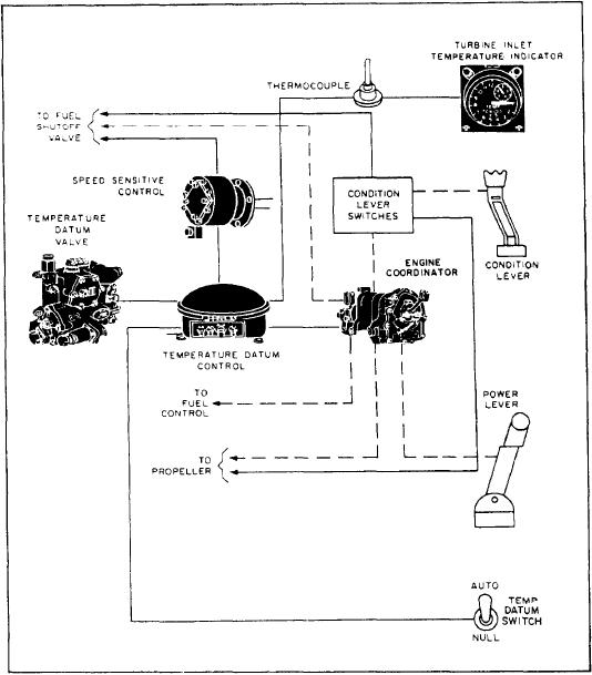
Figure 5-7.-Engine temperature control (turboprop) system block diagram.
changes in fuel density, manufacturing tolerances
power lever is below 66-degree coordinator
in fuel controls, and variations in engine fuel
(temperature limiting range), the normal limiting
requirements between engines. With the power
temperature automatically becomes 978C
lever above 66-degree coordinator (temperature
(1,792F). However, when engine speed is below
94 percent RPM, regardless of power lever
controlling range) and the TEMP DATUM switch
in AUTO, the temperature datum control
position, the limiting temperature is 830C
compares the actual turbine inlet temperature
(1,524F). This prevents high turbine inlet
signal and desired temperature reference signal.
temperature during starting and acceleration when
If there is a difference greater than 1.9C (4.5F),
the compressor bleed valves are open.
Dual-unit thermocouples are mounted radially
the control electrically signals the temperature
in the turbine inlet case of each engine. The
datum valve to reduce or increase fuel flow to the
engine. This action brings the turbine inlet
junction portion of the thermocouples protrudes
temperature to the desired value. A damping
through the case to sense the gas temperature
voltage goes back to the control from a generator
before the gas enters the turbine section. Four
within the temperature valve motor, preventing
leads, two of Chromel and two of Alumel,
overcorrection and stabilizing the system. When
connect to each thermocouple to form two
engine speed is above 94 percent RPM and the
independent parallel circuits. One circuit connects
5-11