
assemblies. The exciter unit's hermetical seal
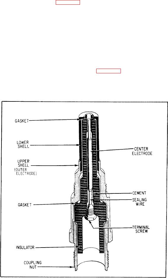
than spark plugs of familiar design. Figure 5-4
shows a typical jet igniter plug.
permanently protects internal components from
moisture, foreign matter, inadvertent maladjust-
ments, pressure changes, and adverse operating
Control of jet ignition systems is through
conditions. This type of construction eliminates
relays or switches that operate automatically
the possibility of flashover at high altitude due
during the engine start cycle. Fuel or oil pressure
switches or centrifugal speed switches energize a
to pressure change and gives positive radio noise
relay to begin ignition. Ignition stops by actuation
shielding. The complete system design, including
leads and connectors, gives adequate shielding
of a centrifugal switch at a speed between 45
against leakage of high-frequency voltage that
percent and 65 percent of rated engine speed.
interferes with radio reception of the aircraft. It
supplies energy to two surface-type spark igniters.
CAPACITOR-DISCHARGE IGNITION
Figure 5-5 is a functional schematic of the
SYSTEM
system. You should refer to this figure when
This ignition system has three major com-
studying the theory of operation of a capacitor-
ponents--one ignition exciter and two lead
discharge system.
Figure 5-4.-Cross-sectional view of a jet igniter plug.