
control pressures and to ease the pilot's workload.
The most common method is the trim tab. Look
at figure 8-8. The figure shows only rudder and
aileron trim tabs. Trim tabs on the elevators on
this particular aircraft are undesirable because
they produce excessive drag. Another method of
elevator trim involves linkage pressure.
When pilots must exert a force on the cockpit
control, they can use the trim control to relieve
that force. For instance, when they must hold left
rudder pressure to prevent yaw movement to the
right, they can move the rudder trim tab to the
right. The airflow on the vertical stabilizer strikes
the trim tab and moves the complete rudder a little
to the left. Since the rudder trim tab now supplies
the required rudder pressure, the pilot no longer
has to hold pressure on the rudder pedals.
ROTARY-WING AIRCRAFT
An aircraft that derives its main lifting force
from a horizontally driven propeller device (rotor)
is a rotary-wing aircraft. The most common
Figure 8-10.-Helicopter flight controls.
rotary-wing aircraft is the helicopter. There must
be relative motion between an airfoil and an air
mass. Therefore, the major advantage of a rotary-
main body of the helicopter from spinning
wing aircraft is its ability to maintain zero or very
(yawing) with the torque of the main rotor. It
low airspeed while the wings (rotors) are still
prevents yaw in much the same way as the
creating lift.
fixed-wing aircraft rudder.
Forces acting on a rotary-wing aircraft are
Collective control maintains or changes
identical to those acting on a fixed-wing aircraft
altitude. Moving the collective control causes an
(fig. 8-6). You must also control the rotary-wing
equal change in pitch (angle of attack) of all main
aircraft about the vertical, longitudinal, and
rotor blades. Also, through a mechanical mixer,
lateral axes, as in figure 8-8.
it automatically changes tail rotor pitch. The
In the conventional helicopter, the main and
collective control changes tail rotor pitch to
tail rotor are engine driven. Remember the earlier
compensate for increases or decreases in main
discussion on airfoils. You increase lift by either
rotor torque. Since the rotor blades are somewhat
increasing the speed of the airfoil through the air
flexible, the more collective control applied, the
or by increasing the angle of attack of the air foil.
more an action called coning takes place. As the
In helicopters, the air foil's angle-of-attack is
blades rotate, they take the shape of a cone
known as blade pitch. When the rotor speed is
(fig. 8-11). The speed and pitch of the blade tips
constant, the pilot maintains complete control of
determines the coning angle. With a constant
the aircraft by varying the pitch of the rotor
blades.
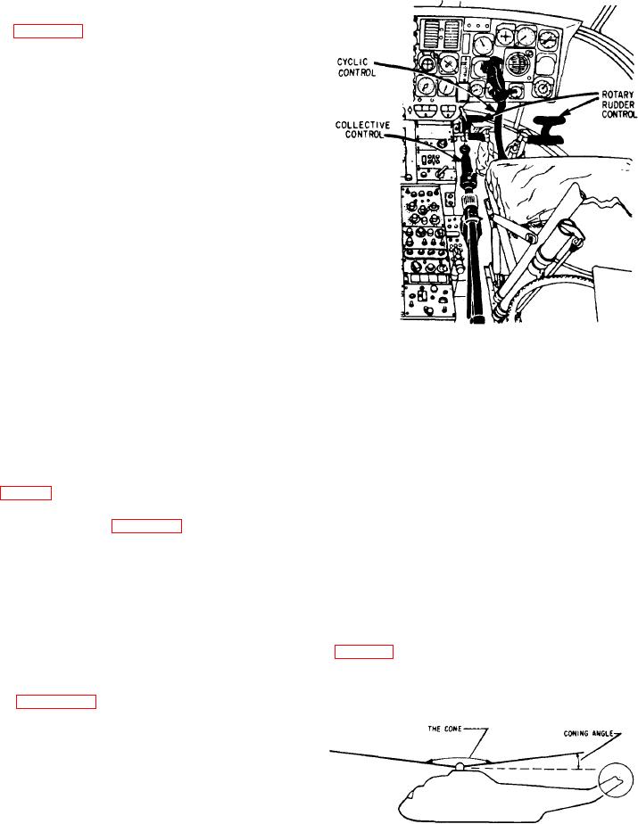
Figure 8-10 shows helicopter flight controls.
The pilot operates collective control with the left
hand, cyclic control with the right hand, and
rudder control with the feet. The collective
and cyclic controls command the main rotor.
Operation of the rudder control changes the blade
angle of the tail rotor.
In helicopter flight (except hovering flight),
the main rotor provides altitude, bank, and
directional control through use of the collective
Figure 8-11.-Coning angle increases as load increases.
and cyclic controls. The tail rotor prevents the